I am wondering if anyone has the pad layout for 7 pin valve socket that can be used with ExpressPCB (component files have .p extension).
ExpressPCB is very easy to use PCB layout tool.
The one for 9 pin would be handy too🙂. It is quite possible that the pin shape and position (my sockets have quite wide pins) may be in the wrong place but it would be a starting point.
I suspect I will end up having to do it all my self.
ExpressPCB is very easy to use PCB layout tool.
The one for 9 pin would be handy too🙂. It is quite possible that the pin shape and position (my sockets have quite wide pins) may be in the wrong place but it would be a starting point.
I suspect I will end up having to do it all my self.
I am wondering if anyone has the pad layout for 7 pin valve socket that can be used with ExpressPCB (component files have .p extension).
ExpressPCB is very easy to use PCB layout tool.
The one for 9 pin would be handy too🙂. It is quite possible that the pin shape and position (my sockets have quite wide pins) may be in the wrong place but it would be a starting point.
I suspect I will end up having to do it all my self.
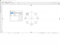
See attached
Attachments
Last edited:
thank you for that; saved me a bit of time calculating position of the pins.
Use a free Cad like eMachineshop, position the part at the dead centre for both software and borrow the co-ordinates into ExpressPCB. This way you can draw any part precisely.
Attachments
- Status
- Not open for further replies.