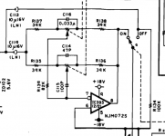
Helo friends I I am building a op amp tone. Controller circuit but this circuit the ic is showen is not available here So I want to use tl072 op amp instead of this ic And Just Want to Know The Connection for Tl072 op amp can any one do it for me??
Thanks in advance..
Thanks in advance..
Attachments
Last edited:

The data sheet is here.
https://www.st.com/resource/en/datasheet/cd00000490.pdf
Note the positive voltage goes to pin 8 and the negative to pin 4 for the common DIP version.
There are two opamps in the package. The first has the output on pin 1. The inverting input is pin 2, this is shown on your schematic as the pin with the circle. Then pin 3 is shown as the non inverting input.
The second opamp has the output on pin 7. On your schematic this is shown as pin 8! The inverting input is pin 6 on your schematic this is shown as pin 7! Finally pin 5 is the non inverting input, shown as pin 6 on your schematic.
i suspect the IC shown in your schematic is not in an 8 pin DIP package. The pin out would be right for the 9 pin inline version. Not commonly available.
Do be careful to get the DIP package not the SOIC version. I suggest you use a socket for the part as there are many different ICs you can actually use.
Last edited:
Thanks Simon For Good ExplanationThe data sheet is here.
https://www.st.com/resource/en/datasheet/cd00000490.pdf
Note the positive voltage goes to pin 8 and the negative to pin 4 for the common DIP version.
There are two opamps in the package. The first has the output on pin 1. The inverting input is pin 2, this is shown on your schematic as the pin with the circle. Then pin 3 is shown as the non inverting input.
The second opamp has the output on pin 7. On your schematic this is shown as pin 8! The inverting input is pin 6 on your schematic this is shown as pin 7! Finally pin 5 is the non inverting input, shown as pin 6 on your schematic.
i suspect the IC shown in your schematic is not in an 8 pin DIP package. The pin out would be right for the 9 pin inline version. Not commonly available.
Do be careful to get the DIP package not the SOIC version. I suggest you use a socket for the part as there are many different ICs you can actually use.
Hi Simon I Tried To make Tone Controller As Shown In My Schematic But It Did Not Work Bcoz I Am Confused With pin 9 or Pin 6 Can U Make A Another Design of this Schematic Using Tl072 Which Includes 8 Pins . Bcoz There Is No Grounding Pin Showing In The Shematic help me Please..🙄The data sheet is here.
https://www.st.com/resource/en/datasheet/cd00000490.pdf
Note the positive voltage goes to pin 8 and the negative to pin 4 for the common DIP version.
There are two opamps in the package. The first has the output on pin 1. The inverting input is pin 2, this is shown on your schematic as the pin with the circle. Then pin 3 is shown as the non inverting input.
The second opamp has the output on pin 7. On your schematic this is shown as pin 8! The inverting input is pin 6 on your schematic this is shown as pin 7! Finally pin 5 is the non inverting input, shown as pin 6 on your schematic.
i suspect the IC shown in your schematic is not in an 8 pin DIP package. The pin out would be right for the 9 pin inline version. Not commonly available.
Do be careful to get the DIP package not the SOIC version. I suggest you use a socket for the part as there are many different ICs you can actually use.
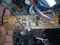
This was pre made In My Amplifier But I Want to Make it Separately For my other ProjectsThe data sheet is here.
https://www.st.com/resource/en/datasheet/cd00000490.pdf
Note the positive voltage goes to pin 8 and the negative to pin 4 for the common DIP version.
There are two opamps in the package. The first has the output on pin 1. The inverting input is pin 2, this is shown on your schematic as the pin with the circle. Then pin 3 is shown as the non inverting input.
The second opamp has the output on pin 7. On your schematic this is shown as pin 8! The inverting input is pin 6 on your schematic this is shown as pin 7! Finally pin 5 is the non inverting input, shown as pin 6 on your schematic.
i suspect the IC shown in your schematic is not in an 8 pin DIP package. The pin out would be right for the 9 pin inline version. Not commonly available.
Do be careful to get the DIP package not the SOIC version. I suggest you use a socket for the part as there are many different ICs you can actually use.
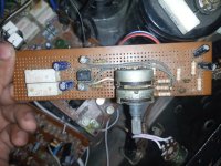
Here is a original
Attachments
- Home
- Source & Line
- Digital Line Level
- Want to use op amp instead of ic in Tone Controller circuit..