I am new to dyi but I thought this would be a good place to start. I have already read this- http://www.tnt-audio.com/clinica/t-amp_tweaks_e.html
I want to do this but put several SI t amps in one box to power speakers in different rooms from one source. I want to keep all the volume controls to control the level in each room.
Questions I have-
1. How to power several amps from one power supply (do not want/need batteries)
2. What will be the best way to connect RC cables so I can have one input leading to the amps.
3. Will heat be a huge issue?
4. How many amps can I reasonably hook up?
just be sure to have only 1 earthing point, for me thats always the star/centerpoint from the caps and transformer.
Multi channel setup
This is a perfect application for a SMPS rated around 120-150W at 12V. This supply will have an adjustment inside to tweak the voltage up to 13.2v. This is the practical maximum the chips will take. This will power 4 of the modules with room to spare. They are available cheap from various sources. You will need to have a buffer cap between the power supply and the modules of around 33,0000uf @ 16v.(This is a minimum more would be better) One twisted wire pair connection from here to the power supply then a pair of twisted wires to each module from the cap. This way all modules see real low source impedance. Try to equalize the wire lengths as this can be important later.
Use the – cap terminal as the star ground point and make a connection from it to the chassis. This will be the only chassis ground connection other than the AC power input 3rd wire ground connection. RCA’s and output jacks all must be insulated from the chassis and only connect to their respective modules. No ground cross connections allowed. Input signal common connections are a problem. You can try connecting them all together to a single RCA forming a complex ground loop but with no other ground connections to the RCA’s and all channels having the same signal this probably won’t be much of a problem. If you do have problems post again with a full description of your setup and the problem for further help.
Roger
Look here for another idea...
Look here for some other ideas. TA2020 is a more powerful amp than the TA2024 in the Sonic Impact Tamp...
http://suburbansurvey.no-ip.org/tripathamp.htm
Look here for some other ideas. TA2020 is a more powerful amp than the TA2024 in the Sonic Impact Tamp...
http://suburbansurvey.no-ip.org/tripathamp.htm
Re: Multi channel setup
Thanks
Lee
Roger, I have a 13.8V Maplin PSU, will this be OK for the T-amp or can I reduce it somehow (as you mention)?sx881663 said:This is a perfect application for a SMPS rated around 120-150W at 12V. This supply will have an adjustment inside to tweak the voltage up to 13.2v.
Roger
Thanks
Lee
Re: Re: Multi channel setup
Lee,
I am not familiar with that supply, not surprising as there are thousands of them out there. Most all follow a common design with the feedback circuit containing an lm431 or equivalent reference. These are usually located near the output connector and will have an adjustment nearby. This is the voltage trim pot and should easily have enough range to get to 13.2v.
If your supply is different please post close-up pictures and I will look it over.
Roger
Lostcause said:
Roger, I have a 13.8V Maplin PSU, will this be OK for the T-amp or can I reduce it somehow (as you mention)?
Thanks
Lee
Lee,
I am not familiar with that supply, not surprising as there are thousands of them out there. Most all follow a common design with the feedback circuit containing an lm431 or equivalent reference. These are usually located near the output connector and will have an adjustment nearby. This is the voltage trim pot and should easily have enough range to get to 13.2v.
If your supply is different please post close-up pictures and I will look it over.
Roger
Re: Re: Re: Multi channel setup
Hi Roger there are two adusters visible on the board.
What do you think?
Cheers
Lee
sx881663 said:
Lee,
I am not familiar with that supply, not surprising as there are thousands of them out there. Most all follow a common design with the feedback circuit containing an lm431 or equivalent reference. These are usually located near the output connector and will have an adjustment nearby. This is the voltage trim pot and should easily have enough range to get to 13.2v.
If your supply is different please post close-up pictures and I will look it over.
Roger
Hi Roger there are two adusters visible on the board.
What do you think?
Cheers
Lee
Attachments
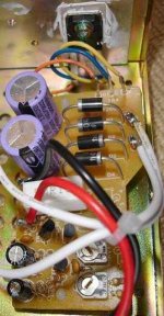
Adjustment pot?
Lee,
In all the supplies I have worked with none had 2 adjusters. One might be for adjusting either a current limit or an over voltage trip point. The other should have a direct connection to the LM431’s adj. point and so should be at 2.5 volts above ground. Measure the wiper on both to ground and see if only one is at 2.5 volts. If this is the case you need go no further and adj. this one to the proper output voltage. If both or neither are at 2.5 volts carefully mark the current position of both, then adj. one of them a little bit to see if the output voltage changes, if it does adj. it to the desired voltage and mark it in some way for future reference. If it doesn’t affect the output return it to its original position and adj. the other one.
Roger
- Status
- Not open for further replies.
- Home
- Amplifiers
- Class D
- Want to re-box several si t amps in one box. How do I hook up to one power supply?