Bricolo said:2V RMS with 96dB dynamic range is something like 30uV for the LSB
not so far from the uV
What is so interesting here ?
Bricolo said:mostly power supplies, and dac outputs
for power supplies you should bandwidth limit the amplifier -- the high pass filter, consisting of the two 1000uF electrolytics and 10K resistor is 100 milliHertz, and the optional high pass filter is 10Hz.
you can make a similar differential or instrumentation amplifier from 3 low-noise opamps -- butyou need to very carefully match the gain setting and feedback resistors. The SSM2019 is about 1/2 the price of an AD797 and is, I believe, primarily aimed at the microphone amplification market.
for testing power supplies -- like the super regs or the Sulzer, etc. it is useful to know the noise in the range of just above DC to 10 Hz -- for the DAC's etc. you obviously don't want to limit the upper range this low (i.e. below audibility.)
a small cookie tin is used by the folks at Linear Tech to shield their low noise power supply testing amplifier.
a small cookie tin is used by the folks at Linear Tech to shield their low noise power supply testing amplifier.
Bricolo said:ok
does a cookie tin mean a cookie metal box?
Yes, the one you keep biscuits in.
Bricolo said:The french post service sucks so much (especially in christmas time) that, at best, you'll recieve an empty cookie tin
...could be worse...in Rome people go to the Vatican to post their letters at Christmas since they have reaonable assurance that they will arrive.
Hi Bricolo,
I have been away for a while hence the late reply. I would recommend the differential amplifier approach, that is what we used in the capacitor tests. It gives you so much versatility like the ability to sample a good local reference point for a true differential measurement. I still keep an old Tektronix 7603 with a set of the differential plug-ins on hand at all times. You can always just ground one input for single ended measuring.
You could make up a three op-amp one or use an integrated one. The current noise of the 797 is too high with source impedances over a few 100 Ohms so be careful. To get more bandwidth you could break up the gain into two parts. A gain of ten in-amp followed by a gain of 1/10/100 amp.
Also don't forget that spectral analysis gives you a big sensitivity advantage. You can really pull tiny signals out of lots of noise. Not everyone realizes that most scopes have a jack in the back that gives you 'what you see'. This way a scope can be used as an input conditioner for a spectrum analyser.
Bric:jackinnj said:all right, if you send me some biscuits from Strasbourg, I will send you a PCB for the SSM2019 !
definitely OT, but a compliment to your city:
http://www.nytimes.com/2005/01/05/dining/05CHOU.html?oref=login
STRASBOURG, France
IN the colder months my mother put sauerkraut on the table once a week. And why not? It was cheap, filling, nutritious, easily stored and true to the culinary heritage of German-American families like ours. "It will put roses into your cheeks," she would tell us kids, and we believed her. We relished every bite.
But it tastes foul, you protest. It smells. It gives you heartburn. Not, I can assure you, when my mother made it, lavishing as much attention on those heaping bowls of steaming preserved cabbage as she would have paid to a prime T-bone or a fine partridge, neither of which appeared very often chez Apple during the Depression
Attachments

I've noticed the thread going a little off topic and just thought I'd throw in some info to get it going again.
I'm in the process of designing a low noise amp that interfaces the real world to a soundcard for a PC-based scope so have been looking at low noise opamps.
It seems to me that the type of measurement will dictate the input stage impedance and hence the desired opamp. If you were to measure high-frequency RF, etc, where 50/75 Ohm termination of scope probes is used it would be prudent to use an opamp with a low input noise voltage - for example a BJT input opamp that makes use of higher input stage currents to lower overall noise. However if you are wishing to make low noise measurements using 1x/10x scope probes (which require a 1M Ohm termination) it is best to use a FET input stage opamp with low noise current and negligable input bias current (at the expense of input noise voltage).
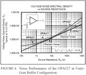
Noise from an opamp has 3 sources (not including the noise source you want to measure!) - these are the thermal noise from the terminating impedance at the opamp input (et), the opamp internal equivalent input noise voltage (en) and the opamp internal equivalent input noise current multiplied by the terminating input impedance of the opamp (inRs).
As can be seen from my attached diagram the equation for the overall noise power from the opamp is a quadratic in Rs. For low input impedance terminations the opamp internal equivalent input noise voltage will dominate and as the terminating impedance is increased it's thermal noise will begin to dominate, then at a certain point the opamp internal equivalent input noise current multiplied by the terminating input impedance will dominate. Hence the terminating input impedance will define what opamp to use - be it a low input noise voltage type (for low input terminations, i.e. 50/75 Ohms) or a low input noise current type (for high input terminations, i.e. 1M Ohm).
I hope this helps!
I'm in the process of designing a low noise amp that interfaces the real world to a soundcard for a PC-based scope so have been looking at low noise opamps.
It seems to me that the type of measurement will dictate the input stage impedance and hence the desired opamp. If you were to measure high-frequency RF, etc, where 50/75 Ohm termination of scope probes is used it would be prudent to use an opamp with a low input noise voltage - for example a BJT input opamp that makes use of higher input stage currents to lower overall noise. However if you are wishing to make low noise measurements using 1x/10x scope probes (which require a 1M Ohm termination) it is best to use a FET input stage opamp with low noise current and negligable input bias current (at the expense of input noise voltage).
Noise from an opamp has 3 sources (not including the noise source you want to measure!) - these are the thermal noise from the terminating impedance at the opamp input (et), the opamp internal equivalent input noise voltage (en) and the opamp internal equivalent input noise current multiplied by the terminating input impedance of the opamp (inRs).
As can be seen from my attached diagram the equation for the overall noise power from the opamp is a quadratic in Rs. For low input impedance terminations the opamp internal equivalent input noise voltage will dominate and as the terminating impedance is increased it's thermal noise will begin to dominate, then at a certain point the opamp internal equivalent input noise current multiplied by the terminating input impedance will dominate. Hence the terminating input impedance will define what opamp to use - be it a low input noise voltage type (for low input terminations, i.e. 50/75 Ohms) or a low input noise current type (for high input terminations, i.e. 1M Ohm).
I hope this helps!
Attachments
... I just found this in a datasheet that illustrates the point (see attached).
However there are some glaring mistakes, for example the log scale on the bottom jumps to 10M ohm (I think it should be 1M ohm) and the scale on the left should read nV per root Hz rather than V per root Hz (I don't much like the idea of an opamp with an equivalent input noise voltage at 1KHz of 100V!!)
However there are some glaring mistakes, for example the log scale on the bottom jumps to 10M ohm (I think it should be 1M ohm) and the scale on the left should read nV per root Hz rather than V per root Hz (I don't much like the idea of an opamp with an equivalent input noise voltage at 1KHz of 100V!!)
Attachments
I built that kind of like thingie from 3 OP37 opamps, each one at gain of 10. Combined with PC soundcard and FFT progs I can measure down to about 3nV. Cookie tins and copperclad(PCB) boxes ala Pease are absolute neccessity at this level. Even then I need to connect it to PC with 3m++ coax cable as CRT display is spraying multiples of 85hz interference and run around my room to find quietest corner. Gonna need steel box with 1" walls soon... ")
we were battin' this around on another thread -- i think you can go even one better with a first stage consisting of 3 or more paralleled 2sk170 or LSK170's -- probably sub nano-volt. these things cook, however.
as you correctly point out, when you get into the 10e-9's even moving a cable, will greatly influence results.
as you correctly point out, when you get into the 10e-9's even moving a cable, will greatly influence results.
If you can, try and find a copy of "Low-Noise Electronic System Design", by C. D. Motchenbacher, J. A. Connelly. It will give you all you need to understand noise in electronic circuits and an excellent tutorial on how to measure noise.
I am in the process of building the circuit that the authors used for their noise measurements. The amp has a gain of 60dB (1000x), small signal bandwidth of 0.3Hz to 500kHz and En = 2.5nV/squarerootHz. It is designed for use with source impedances up 1Mohm. This would make it more universally useful than a circuit based on the SSM20xx series which are typically designed for source impedances (well) below 1kohm.
Or build both!
This one is for work so it has an SMA input (this is so I can use a commercial 50ohm coaxial cable that I solder directly onto the pcb that i'm testing) and 50ohm BNC output for connection to my scope. If you would like the pcb file when I'm done I'm happy to provide it.
- Status
- This old topic is closed. If you want to reopen this topic, contact a moderator using the "Report Post" button.
- Home
- Design & Build
- Parts
- Want to measure µV on the scope: should I buy a new one or build a low noise preamp?