I noticed a big mistake in the design of the output bias circuit. At the minimum you really, really need some high quality capacitors from the bias pot wipers to ground. Better still do what I suggest a couple of lines further along in this post. The transformer secondaries are floating off the 22K pots and the source impedance as well as ac signal level seen at the grids will differ depending on the position of the wiper. This is meant to be a dc adjustment only as well. I would recommend inserting a 50K resistor between the bias pot wiper and the secondary of the interstage transformer, in addition I would recommend installing about a > 0.33uF film cap from the cold end of each winding to the cathode return of the output tubes. This will provide a very well defined ac ground at the cold end of the driver transformer. Should sound a lot better too as the non-linearity of the wiper will not be an issue.. Your measured phase shift is related to the current configuration as well.
Kevin
Edited to improve clarity
Kevin
Edited to improve clarity
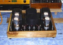


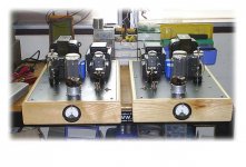
Whoa, some beautiful BIG work on those beautiful tubes...
yes, I like them BIG 😉
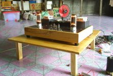
the pictures with the lights off are AWESOME IMHO. I wish one day to build an amp like that...
yes, I like them BIG 😉
the pictures with the lights off are AWESOME IMHO. I wish one day to build an amp like that...


Woohhh!!!
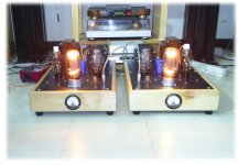
Very nice work. Is is sound as good as it looks like also?
I'm thinking of building one like this 417A DC coupleed to 300b IT LL1677 (80mA Vesrion) GM70.
Will you share with us the schematics? Whut are you using for OPT?
Very nice work. Is is sound as good as it looks like also?
I'm thinking of building one like this 417A DC coupleed to 300b IT LL1677 (80mA Vesrion) GM70.
Will you share with us the schematics? Whut are you using for OPT?

- Status
- Not open for further replies.
- Home
- Amplifiers
- Tubes / Valves
- want to do PP-GM70