H.T.S.,
Using resistors in water is not about insulation on the wires down to them. (I doubt you can seal it all up, and maintain good thermal contact with the water).
It's more that if the voltage gets high enough, you'll have significant conductance of current in the water, along the outside the resiatoe enclosure. I haven't met this problem yet, though. also, it'll not be a complete short circuit, and it will cease as the voltage is lowered by the increased load. If in doubt, test at 50Hz signals and with a high-current ampere-meter in series to ensure you have the expected current.
Jennice
Majord,
“sorryt ot hear about ur problems with the p3, i dont have any ideas not having a good understanding of indepth symptoms. but first things first do u have 1 or 2 amp boards? if 2 , are they both giving the same problem?”
I have constructed a two channel board both channels have the same distortion at low power the more so the closer the input and output come to unity. Or so it seems.
I am just learning how to use my new toy a stingray usb oscilloscope.
Using the stingrays inbuilt sine wave generator.
The output from the longtailed pair at r4,r5
and base of q2.
The distortion (input differs from output) is when the input voltage drops below 220mV.
At 125 and 59mV the FFT input is different from the output. (220mV and above
it is ok)
Please note: anyone reading this not familiar with this amp, that great number of these amps have been built and have worked first time.
Hitsware,
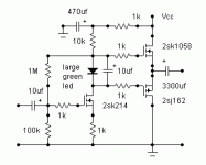
I can see that you are into minimalism in a big way 😉
What value is Vcc?
Is this amp class B?
I can see that you are into minimalism in a big way 😉
What value is Vcc?
Is this amp class B?
>What value is Vcc?
With Vcc ~ 28V it will nicely warm a couple of 'board level' heatsinks and do a comfortable 5 Watts.
>Is this amp class B?
'AB' ......... ~100ma. idle current. The LED has a drop of ~1.65 V .................(the Hitachi devices have a much lower threshold voltage than IR types (and are temperature stable))
Hi Hitsware,
Are suggesting this amp as a candidate for a first amp?
What is the purpose of posting it here?
Is there something about it that pertains to the discussion?
I must admit, I'm not to the point of building from a schematic just yet. Hopefully someday however.
Blessings, Terry
Are suggesting this amp as a candidate for a first amp?
What is the purpose of posting it here?
Is there something about it that pertains to the discussion?
I must admit, I'm not to the point of building from a schematic just yet. Hopefully someday however.
Blessings, Terry
>Are suggesting this amp as a candidate for a first amp?
Yes.
>What is the purpose of posting it here?
See above.
>Is there something about it that pertains to the discussion?
I thought so, but perhaps not ? 😕
Yes.
>What is the purpose of posting it here?
See above.
>Is there something about it that pertains to the discussion?
I thought so, but perhaps not ? 😕
hitsware said:>Are suggesting this amp as a candidate for a first amp?
Yes.
>What is the purpose of posting it here?
See above.
>Is there something about it that pertains to the discussion?
I thought so, but perhaps not ? 😕
Sorry if that came off wrong. I'm not learned in schematics. I can't tell by looking at your drawing what it represents.
Are there PCB's for this?
What are the specs?
Thanks, Terry
HuntTheShunt,
You'll always have some level of distortion in an amp. If you have too low idle/bias, it'll show clearly on the FFT.
Jennice
You'll always have some level of distortion in an amp. If you have too low idle/bias, it'll show clearly on the FFT.
Jennice
OK, well I got it all together. As I have said, I had already tested the boards prior to installing them to the heatsinks so I went ahead and installed them and hooked everything up. I hooked the amp up to my variac and began bringing up the voltage. At about 35V I could hear the softstart circuit kick in and I began to read voltage at the filter caps. I then checked for voltage at the speaker outputs. This is what I read.
Channel #1 = 10.7 mV
Channel #2 = 10.7 mV
Channel #3 = 43V
I shook my head and checked again. Yep, channel 3 is reading the same voltage as the rails.
I shut everything down and pulled out the board. As I inspect it I see that a splash of solder is between ZD1 and D1. a drop must have fallen off of my soldering iron during the installation. Anyway I cleaned out the solder and hooked it back up to the caps and get the same thing. 🙁
Have I ruined the MOSFETS?
Is there a way to check them quickly?
Good news is that the other two channels are playing beautifully. I am listening to them as I type this. The definition is really good. Not quite the low end punch that my Haflers have but the high end is very clear and defined.
I'll post some pics shortly.
Please give me some ideas for getting the third channel fixed.
Thanks, Terry
I had the same questiob with BJTs until I bought an incircuit tester on ebay. Prior to that, a quick way that may apply to MOSFETS as well is to measure the resistance between all combinations of pins (B, C & E or in you case G, S & D) on one of the working boards. Then do the same on the non-working board. Anything markedly different is highly suspect, but watch for components in parrallel as it then becomes ambiguous which component is as fault.
While you are measuring resistances, check all the resistors again to be sure you got the right ones in the right place or that the fault did not damage one.
One thing I try to avoid is poking around with a probe noting voltages. Usually it doesn't tell me anything helpful (everthing has gone hard to the rails) and eventually I get a little cumbsy and short something with the probe itself. If I must find a voltage, I connect hooks or alligator clipd when powered off then stand back and switch the power back on.
Meanwhile -- rejoice at the good news - two boards are working so you know that the approach is correct in concept and principle. When you don't kinow if the problem is construction or design that is very tough!
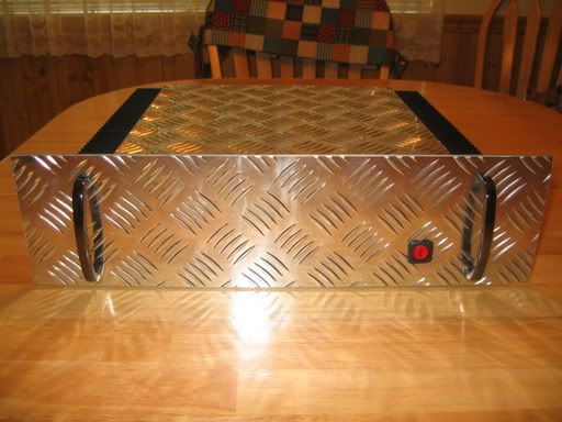
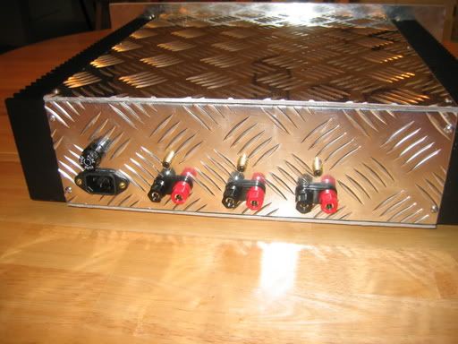
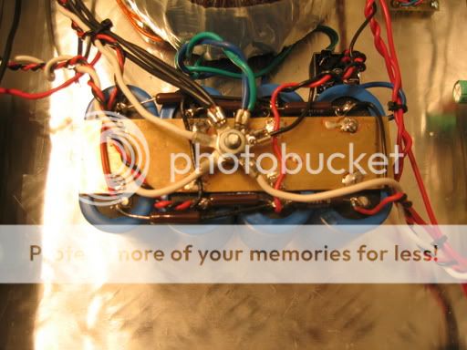
OK, as promised, here's some pics of my new amp;
If you have been following this thread, you know I intended this to be three channels. One board has problems so I'm running it as a stereo right now. I will reinstall the other board as soon as I have it worked out.
I'll warn you, it's a little different than what you might see at your local audio shop. 😀

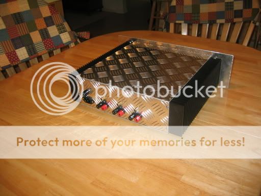
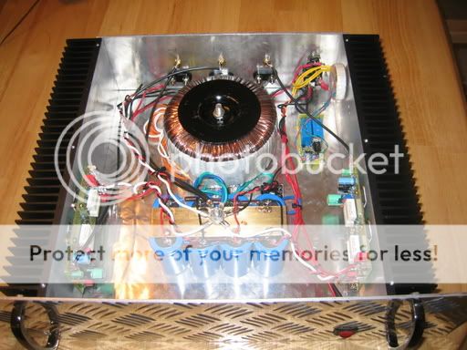
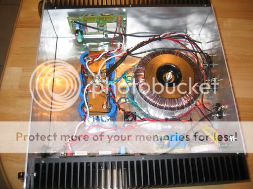
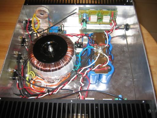
Soft start circuit;
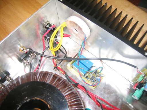
Feel free to ask questions.
Blessings, Terry
If you have been following this thread, you know I intended this to be three channels. One board has problems so I'm running it as a stereo right now. I will reinstall the other board as soon as I have it worked out.
I'll warn you, it's a little different than what you might see at your local audio shop. 😀
Soft start circuit;
Feel free to ask questions.
Blessings, Terry
very nice
the case looks kind off weird 😀 those metal sheets look like parts of an elevator plour or something
the case looks kind off weird 😀 those metal sheets look like parts of an elevator plour or something
Hey Still4given,
The amp looks great. It looks like your running the same setup that I’m in the process of building. I have one really quick question. How much did it cost to ship the heatsinks from Conrad. I live in Oregon so the cost would probably be similar and they have failed to return my email requesting the shipping charges.
Thanks
Brian

Killjoy99,
I've bought a couple of Conrad 'sinks. Different model. I don't remember the exact cost of shipping to California except that it was about the same as the 'sink itself. Regardless, it was still cheaper than MM-Metals which is the only US source I know of where you can buy in halfway reasonable quantities.
I've bought a couple of Conrad 'sinks. Different model. I don't remember the exact cost of shipping to California except that it was about the same as the 'sink itself. Regardless, it was still cheaper than MM-Metals which is the only US source I know of where you can buy in halfway reasonable quantities.
Sam9, I used UPS's and FedEX's website to calculate what the shipping may cost from there address and like you said it is about the cost of the heatsinks themselves.
I already have a case designed based around two of their heatsinks so it's pretty much decided that I'll go with Conrad either way. Just trying to estimate the cost before I go all in, lol.
Thanks
Brian
I already have a case designed based around two of their heatsinks so it's pretty much decided that I'll go with Conrad either way. Just trying to estimate the cost before I go all in, lol.
Thanks
Brian
DOH! (just typed a long post, and pushed the wrong button)
Anyway,
I think you've come a really long way Terry! In less than 3 months and 237 posts, you have gone from the "wish to DIY" to having two channels playing music! Really well done! You've got every reason to feel proud!
That enclosure shouts "I'm BAD!" to me
As for safety, I think you should give that extra soft-start-transformer (the one on the heat sink, if that is a mains transformer) its own fuse. If this small transformer runs on the same fuse as the big one, the small transformer will melt down before the fuse blows.
Jennice
Beautiful job Terry, it gives me encouragement to continue with my project. Well done.
thanks
Clint
keep us posted on channel 3
thanks
Clint
keep us posted on channel 3
The amp looks great. It looks like your running the same setup that I’m in the process of building. I have one really quick question. How much did it cost to ship the heatsinks from Conrad. I live in Oregon so the cost would probably be similar and they have failed to return my email requesting the shipping charges.
Thanks Brian,
Here's what Julian sent me.
MF25-151.5 x 2 @ 40.22 ea. 80.44 (62.74)
Delivery (Aus. Post Air 7-10 w. days) 49.82 (38.86)
Delivery (Aus. Post Standard Air 2-6 wks.) 36.82 (28.72)
Availability: in stock
I did the post air because I didn't want to wait that long. Took about a week to receive them.
As for safety, I think you should give that extra soft-start-transformer (the one on the heat sink, if that is a mains transformer) its own fuse. If this small transformer runs on the same fuse as the big one, the small transformer will melt down before the fuse blows.
Thanks Jens,
I will look into adding a fuse for the soft start trans.
Beautiful job Terry, it gives me encouragement to continue with my project. Well done.
keep us posted on channel 3
Thanks Clint,
I'm still hoping someone can give me an idea where to start looking for the problem. I've inspected the board and I don't see any more solder bridges. I'm hopeful that I didn't ruin one or more of my output transistors. Could that cause the high voltage reading at the speaker outputs?
Thanks, Terry
- Status
- Not open for further replies.
- Home
- Amplifiers
- Solid State
- Want to build my first amp