This will be my first ever adventure into the world of diy audio, not counting my diy speakers (Made those when I was younger and didn't have a clue what I was doing). I do have an education as an electronics mechanic, but I have spent most of my time in the digital realm. Lots of ones and zeroes and assembly programming, but not much of the analog stuff. I have of cause been taught about filters and amplifiers, but over the years it's been banished to the darkest most dusty corners of my memory. I hope my love for Hi-Fi and my recent urge to give diy audio a go, will change that. It should be a healthy experience 🙂
Bear with me if I ask a lot of stupid questions 😀
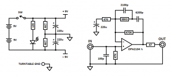
So, I've bought a set of PCBs from chipamp.com and have planned to build some sort of amplifier setup. But I thought I'd start with something a little smaller. A RIAA compensated preamp for my darling SL-1210II. I'd like to make it tiny and simple. The phono preamp at paia.com caught my eye. Simple construction (but is it any good?) with only a few components in the signal path. I was thinking about making a sort of hybrid between this and the CMoy headphone amp. Basically just using the CMoy PSU.
I'd change the value of the caps as suggested in this thread:
http://www.diyaudio.com/forums/anal...thout-confusing-riaa-stuff-2.html#post2089453
and power the amp with two 9v batteries.
Will 2x 9v be sufficient, or will the amp suck them dry in no time?
One question I have is about grounding. There's both the ground wire from the turntable, the two signal grounds, the chassis of the preamp and the zero volt line between the batteries. Which of these should be connected to each other?
I'm also not quite certain about the value of the 220uF cap in the amp filter network. As far as I understand, it needs to hit a good compromise between a tolerable bass definition and a decent rumble filter? Would 100uF be a better choice?
Please let my know if I've missed anything vital 😀
Bear with me if I ask a lot of stupid questions 😀
So, I've bought a set of PCBs from chipamp.com and have planned to build some sort of amplifier setup. But I thought I'd start with something a little smaller. A RIAA compensated preamp for my darling SL-1210II. I'd like to make it tiny and simple. The phono preamp at paia.com caught my eye. Simple construction (but is it any good?) with only a few components in the signal path. I was thinking about making a sort of hybrid between this and the CMoy headphone amp. Basically just using the CMoy PSU.
I'd change the value of the caps as suggested in this thread:
http://www.diyaudio.com/forums/anal...thout-confusing-riaa-stuff-2.html#post2089453
and power the amp with two 9v batteries.
Will 2x 9v be sufficient, or will the amp suck them dry in no time?
One question I have is about grounding. There's both the ground wire from the turntable, the two signal grounds, the chassis of the preamp and the zero volt line between the batteries. Which of these should be connected to each other?
I'm also not quite certain about the value of the 220uF cap in the amp filter network. As far as I understand, it needs to hit a good compromise between a tolerable bass definition and a decent rumble filter? Would 100uF be a better choice?
Please let my know if I've missed anything vital 😀
Attachments
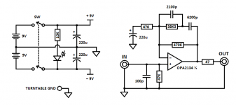
Your batteries will not last long. It is better to connect GND to the center of the batteries and remove the 4.7k resistors, also use a two-pole switch. The 220u capacitor is sufficient, in fact anything above 22u would do.
Look at ian's fifo project (digital line sub forum), he's developing a nice battery management board for switching between battery charge/battery supply. It's "universal" so it will be a nice addon.
Look at ian's fifo project (digital line sub forum), he's developing a nice battery management board for switching between battery charge/battery supply. It's "universal" so it will be a nice addon.
Nahh, I won't be making it that advanced. It's just a small simple project to get me started. Probably won't be long before I replace it with a P05 + P06 combination from Elliott Sound Products 🙂
It is better to connect GND to the center of the batteries and remove the 4.7k resistors, also use a two-pole switch.
So this would be a better design:
the obvious may be ...
...the P06 from ESP, or a Hagerman Bugle kit or similar. The circuit shown seems pretty reasonable. Just remember that the idea is to sum 3 filters for the desired response. The time constants are:
What next to add to the (passive) circuit as described above? The rest is providing a power supply, and suitable loading (both resistive and capacitive) and an output gainstage. After that, add some options:
This "scheme" allows for MC and MM and is as simple as it can get, and is derived from the RIAA specification for playback.
PS: I'm no designer so take it with a grain of salt, or a lb. 😉, but was derived solely from the RIAA spec.
...the P06 from ESP, or a Hagerman Bugle kit or similar. The circuit shown seems pretty reasonable. Just remember that the idea is to sum 3 filters for the desired response. The time constants are:
- LR tc (parallel)= 3180 μsecs
- RC tc (series) = 318 μsecs
- RC tc (parallel)= 75 μsec
What next to add to the (passive) circuit as described above? The rest is providing a power supply, and suitable loading (both resistive and capacitive) and an output gainstage. After that, add some options:
- a gain stage in front of the equalizer circuit
- a switch between the above gain stage and the equalizer, and the second position of the switch bypassing the gain stage
This "scheme" allows for MC and MM and is as simple as it can get, and is derived from the RIAA specification for playback.
PS: I'm no designer so take it with a grain of salt, or a lb. 😉, but was derived solely from the RIAA spec.
Last edited:
You might want to DC couple the input (eliminate the 220uF electrolytic) and place a blocking cap (10uF) on the output -- this will save space and improve the performance at the low end. You can make the amplifier a little less noisy by reducing the resistor values by a factor of 6, increasing the capacitor values by 6. -- and if you use 5.8 you'll get the exact values in Jung's "Op Amp Handbook"
You might want to DC couple the input (eliminate the 220uF electrolytic) and place a blocking cap (10uF) on the output -- this will save space and improve the performance at the low end.
But the amp is DC coupled (both input and output)?
You can make the amplifier a little less noisy by reducing the resistor values by a factor of 6, increasing the capacitor values by 6. -- and if you use 5.8 you'll get the exact values in Jung's "Op Amp Handbook"
Too late. I've already bought most of the caps 🙂
- Status
- Not open for further replies.
- Home
- Source & Line
- Analogue Source
- Want to build a tiny battery powered RIAA