Member
Joined 2018
Hello Folks,
I sometimes feel frustrated by the small number of controls on my FreeDSP Classic SMD A/B. ADAU1701 has only four AUXADC for reading control POTs. Well, the ADAU1452/1466 has six AUXADCs. However, in many cases, ADAU1701 is enough for processing. But the control is not enough...
So I start a small project for expanding AUXADC on ADAU1701. The basic idea is to use an external MUX circuit driven by feeding the POT selection signal from the DSP. Unselected POT keeps holding a last-moment value during the opposite POT reading.
The AUXADC multiplexer circuit:
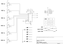
Multiplexer Circuit Switching Test Result
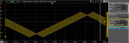
SigmaStudioPrototyping
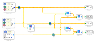
DAC Output
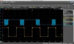
It seems possible to implement AUXADC multiplexing. So I will start the board design...
CyberPIt
I sometimes feel frustrated by the small number of controls on my FreeDSP Classic SMD A/B. ADAU1701 has only four AUXADC for reading control POTs. Well, the ADAU1452/1466 has six AUXADCs. However, in many cases, ADAU1701 is enough for processing. But the control is not enough...
So I start a small project for expanding AUXADC on ADAU1701. The basic idea is to use an external MUX circuit driven by feeding the POT selection signal from the DSP. Unselected POT keeps holding a last-moment value during the opposite POT reading.
The AUXADC multiplexer circuit:

Multiplexer Circuit Switching Test Result

SigmaStudioPrototyping

DAC Output

It seems possible to implement AUXADC multiplexing. So I will start the board design...
CyberPIt
Attachments
Member
Joined 2018
Attachments
Last edited:
Member
Joined 2018
Member
Joined 2018
I did parts mounting today. There was a mistake...
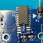
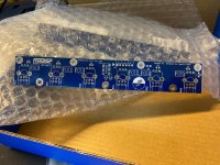
It was too narrow. But I soldered it anyway.
Then a board is ready to evalute.
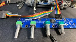
Evaluation project of reading two pods with one AUXADC simultaneously.

A timing check result.
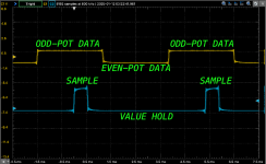
Finally, Now I can read 6+1=7 pots simultaneously with ADAU1701. A tough limitation was gone.
CyberPit


It was too narrow. But I soldered it anyway.
Then a board is ready to evalute.

Evaluation project of reading two pods with one AUXADC simultaneously.
A timing check result.

Finally, Now I can read 6+1=7 pots simultaneously with ADAU1701. A tough limitation was gone.

CyberPit
Member
Joined 2018
I did a full function test with FreeDSP Classic SMD A/B board.

Just connect to J1 with a ribbon cable.
A hierarchy SigmaStudio Project was made.

The root layer project is like this way.

A timing check result

It worked as I expected!
Another evaluation, 6-Bands Graphic-EQ like project...

Also worked fine.
I will make a GIt-Hub page soon...
CyberPit
Just connect to J1 with a ribbon cable.
A hierarchy SigmaStudio Project was made.
The root layer project is like this way.
A timing check result
It worked as I expected!
Another evaluation, 6-Bands Graphic-EQ like project...
Also worked fine.
I will make a GIt-Hub page soon...
CyberPit
Attachments
Last edited:
Member
Joined 2018
Member
Joined 2018
Good Question!
I measured with my FreeDSP Classic SMD A/B.
Embedded ADC (2.0V RMS Input) to DAC through the DSP.

Turn off the signal source, but still ADC through to the DAC. (All pots at the 12 o'clock position)

Odd POT MAX and Even POT min

There are small crosstalk (-110dB) and its harmonics exist. This might be coming from the on-chip coupling between the AUXADC and the Embedded Audio ADC. It's not so big, but Maybe this crosstalk level will decrease if the POT switching rate sets slow.
CybrePit
I measured with my FreeDSP Classic SMD A/B.
Embedded ADC (2.0V RMS Input) to DAC through the DSP.
Turn off the signal source, but still ADC through to the DAC. (All pots at the 12 o'clock position)
Odd POT MAX and Even POT min
There are small crosstalk (-110dB) and its harmonics exist. This might be coming from the on-chip coupling between the AUXADC and the Embedded Audio ADC. It's not so big, but Maybe this crosstalk level will decrease if the POT switching rate sets slow.
CybrePit
Can you try with 4 channel 2:1 multiplexer for 8 control potentiometers?
Later tonight I'll share an another idea, without multiplexer.
Later tonight I'll share an another idea, without multiplexer.
Member
Joined 2018
dzwer-San,

Non-precise but only a few parts for multiple POT reading ideas.

Of course, 3 more POTs and diodes are able to be connected to each GPIO.
CyberPit
Yes, It's possible, if I use the 2 boards. Just connect MP0 in parallel. I wonder the HC4053 has three SPDT circuits, so using two HC4053 and two control lines will enable to read 10 POTs logically.Can you try with 4 channel 2:1 multiplexer for 8 control potentiometers?

Non-precise but only a few parts for multiple POT reading ideas.
Of course, 3 more POTs and diodes are able to be connected to each GPIO.
CyberPit
Just I've thought!
But with inverters on 4 MP output pins to 8 pots and to the 4 AUX ADCs.
But actually we can use only the 2 MP output pins(or only 1 with simple BJT/MOSFET inverter), as you drown, with 4 + 4 parallel pots to the 4 AUX ADCs.
I have to check what is the max output source current for these MP pins.
Edit: When set as an output, each pin can typically drive 2 mA.
Last edited:
Idea schematic:

Diodes D1-D8 should be Shottky and the op amps(or comparators) should be with reail-to-rail outputs(LM358 is not).
Diodes D1-D8 should be Shottky and the op amps(or comparators) should be with reail-to-rail outputs(LM358 is not).
Member
Joined 2018
Hi dzwer-San,
The right half part op-amp's positive input voltage should be half of the logic-high level. (=1.65V)
However, I recommend using HC04/14 or LV04/14 CMOS logic IC for this design.
To eliminate the near-zero area of non-linearity, an idea is to add one more diode like this way...

CyberPit
The right half part op-amp's positive input voltage should be half of the logic-high level. (=1.65V)
However, I recommend using HC04/14 or LV04/14 CMOS logic IC for this design.
To eliminate the near-zero area of non-linearity, an idea is to add one more diode like this way...
CyberPit
These are perfect:
SN74LVC1G17 Single Schmitt-Trigger Buffer
SN74LVC1G14 Single Schmitt-Trigger Inverter
SN74LVC1G17 Single Schmitt-Trigger Buffer
SN74LVC1G14 Single Schmitt-Trigger Inverter
Last several days I found in different forums, that SigmaStudio is working properly on some Windows 10 machines and on the others there is USB communication problems.
I have this issue on Lenovo L440 laptop with a clean installation of Windows 10 Pro and SigmaStudio 4.7 - the newest version and several ADAU1701 DSP boards. The driver for the USBi is installed and in the SigmaStudio is in green. I can read/write the EEPROM on the DSP board, but I can not connect to the DSP. Tested with several blue CY7C68013A mini boards with 1 and 2 jumpers on them and with several DSP boards, that I know are working properly.
I resolved the issue as I installed a VMWare Player and a Windows 7 Virtual Machine in which I installed the same SigmaStudio 4.7.
Everything worked from the first try and on the same laptop!
- Home
- Source & Line
- Digital Line Level
- Want more control POTs on ADAU1701?


