Can somebody tell me if this diode will suffice for D1 through D4?
http://search.digikey.com/scripts/DkSearch/dksus.dll?Detail&name=568-1362-1-ND
http://mysite.verizon.net/tammie_eric/audio/jig2/jig2.html
http://search.digikey.com/scripts/DkSearch/dksus.dll?Detail&name=568-1362-1-ND
http://mysite.verizon.net/tammie_eric/audio/jig2/jig2.html
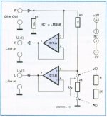
The diodes are not normal diodes; notice the 'z'-shaped bar connected to the arrow in the diagram.
These are Zener diodes which means they will hold a specific voltage very much like a voltage regulator. In fact, they are frequently used as a reference voltage in a voltage regulator.
The diodes in question appear to be 5.1v 1W Zener diodes.
This mean any incoming signal over 5.1 volts will be clamped at ±5.1v. This prevents over voltage on the inputs. (Actually, it is clamping at 5.7v, but let's not complicate the issue with details.)
Trying to search anything out from Digi-Key is very difficult. However, if you have the printed catalog, it shouldn't be too hard to find a 5.1v 1w Zener Diode.
Try this Digi-key part number - 1N4733ADICT-ND ... 5.1v 1w Zener at $.44 each. (page 1282 in the catalog)
Keep in mind that the voltage isn't critical. Agian, it is just acting as a limiter or over voltage protection on the input. Likely any thing in the range of 4 to 7 volts would work fine.
Steve/bluewizard
Re: here is something even better
Yes those will work.
It does. D1-D4 is just extra protection in case you muff it.
But then it would be a "mcmahon jig" and nobody would use it cos it would never be explained properly. and all the "ins" and "outs" would be all so mixed up.
correct +3
454Casull said:Can somebody tell me if this diode will suffice for D1 through D4?
Yes those will work.
soongsc said:I would vote to use a voltage divider instead of diodes if you know the voltage gain of the amplifier you use.
It does. D1-D4 is just extra protection in case you muff it.
mcmahon48 said:you will get much better results and it is very inexpensive and a lot easier to build
But then it would be a "mcmahon jig" and nobody would use it cos it would never be explained properly. and all the "ins" and "outs" would be all so mixed up.
BlueWizard said:
The diodes in question appear to be 5.1v 1W Zener diodes.
Trying to search anything out from Digi-Key is very difficult. However, if you have the printed catalog, it shouldn't be too hard to find a 5.1v 1w Zener Diode.
Keep in mind that the voltage isn't critical. Agian, it is just acting as a limiter or over voltage protection on the input. Likely any thing in the range of 4 to 7 volts would work fine.
Steve/bluewizard
correct +3
It is not my jig but it is easy to understand
the lines in are to the sound card input and where the two resistors are to the one op amp input is your calibration resistor and the out of course is from the speaker I modified by using a precision potientometer instead of switch out resisitors
a lot more compact and can use batteries with it like to AA or C, D, or 9v with a regulator package thrown in
Correct +3 -1= 2
Re: It is not my jig but it is easy to understand

Anyway, my line-in clips at well under 1V. Is there a reason why Wallin likes 5.8V?
Was that one sentence?mcmahon48 said:the lines in are to the sound card input and where the two resistors are to the one op amp input is your calibration resistor and the out of course is from the speaker I modified by using a precision potientometer instead of switch out resisitors
a lot more compact and can use batteries with it like to AA or C, D, or 9v with a regulator package thrown in
Correct +3 -1= 2
Anyway, my line-in clips at well under 1V. Is there a reason why Wallin likes 5.8V?
Q - Anyway, my line-in clips at well under 1V. Is there a reason why Wallin likes 5.8V?
PC sound card chips run at +5V?, maybe he was aiming for 5V initially. So using Vz = 4.3 would be more closer? BWizard has it right
check this app note about protecting audio interfaces http://www.onsemi.com/pub_link/Collateral/AND8245-D.PDF
PC sound card chips run at +5V?, maybe he was aiming for 5V initially. So using Vz = 4.3 would be more closer? BWizard has it right
check this app note about protecting audio interfaces http://www.onsemi.com/pub_link/Collateral/AND8245-D.PDF
Like I said, my line-in clips at under 1V. Would it be a problem if I were to use red LEDs to keep the voltage under ~1.7V as in the version 1 jig?infinia said:I suppose high voltages from a poweramp can melt some line ins on a PC. fail safe for gomers
PC sound card chips run at +5V?, maybe he was aiming for 5V initially. So using Vz = 4.3 would be more closer? BWizard has it right
Then the Vpeak across BP3-4 would be 17V, thus allowing me to use 1/4W values for all the other resistors (as long as their values did not change).
EDIT: Also, does anybody know why Wallin picked the resistance values that he did? For the voltage dividers, he could've used 1k with 100R and 316R for the -20dB and -10dB measurements. I can see 1.175K and 130.1R, I suppose, but what does the 543.2R R6 do?
And for the calibration resistors... well, are 16.2R and 4.05R the recommended resistances to use with SW? EDIT2: So he says that the absolute values for R4 and R5 are not important. Cool.
Oh, totally sweet, dude. I'm gonna use that thread instead of this one then.MJL21193 said:This thread might be of interest.
- Status
- This old topic is closed. If you want to reopen this topic, contact a moderator using the "Report Post" button.
- Home
- Loudspeakers
- Multi-Way
- Wallin Jig v2 for Speaker Workshop