Hi, I've been reading lots about dipoles, hframes etc. I like the W Frame that's listed on Linwwitz site (Phoenix). He uses 2x 12" woofers.
I have on hand 4 Eminence Eminator 2515, I've been considering various alignments for a long time; but I finally have wood now too, so I'm close to cutting now.
These drivers appear to me to have Qts, Fs, and Le that would be appropriate for a dipole, so I may give it a try.
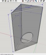
Here's my questions. Please refer to attached pic. The pic is the Linqwitz "plan". I want to be able to use 15" woofers.
Can I simply increase the dimension of panel "D" to something like 17" x 19" to accommodate 15" driver?
Do I understand correct that the "tuning" of the box is mostly determined by the length of panel "A"?
My theorie is that if I leave panel A at 19", that this determines the length of separation between the front wave and back wave. Also it controls the length of the 1/4 wave inside the box. Therefore, if I don't change that length, it should work.
am I on the right track, or should I scale the entire box larger? I have not found a w-frame sim or other design tool yet.
Looking forward to replies.
I have on hand 4 Eminence Eminator 2515, I've been considering various alignments for a long time; but I finally have wood now too, so I'm close to cutting now.
These drivers appear to me to have Qts, Fs, and Le that would be appropriate for a dipole, so I may give it a try.
Here's my questions. Please refer to attached pic. The pic is the Linqwitz "plan". I want to be able to use 15" woofers.
Can I simply increase the dimension of panel "D" to something like 17" x 19" to accommodate 15" driver?
Do I understand correct that the "tuning" of the box is mostly determined by the length of panel "A"?
My theorie is that if I leave panel A at 19", that this determines the length of separation between the front wave and back wave. Also it controls the length of the 1/4 wave inside the box. Therefore, if I don't change that length, it should work.
am I on the right track, or should I scale the entire box larger? I have not found a w-frame sim or other design tool yet.
Looking forward to replies.
Attachments

What makes you think these driver specs are appropriate for a dipole? The fs and qts do not allow a simple 2nd order crossover so dsp is going to be required. And the 6 mm xmax isn't much for a dipole sub.
The slots are going to create a cavity resonance, that's not the "tuning", this resonance will occur higher up in frequency, hopefully above your intended passband. The longer the cavity is, the lower in frequency the resonance will occur. Unless you simulate the effect and have a plan to deal with it, you ideally want the cavity(s) to be as short as possible to push the resonance as far above the passband as possible.
This paper explains a bit about how U and H frames work. http://www.quarter-wave.com/OBs/U_and_H_Frames.pdf
Note that they ONLY way he was able to achieve a flat passband with a simple 2nd order filter is because he wisely chose a high qts driver with a reasonable (high) fs. if you have dsp none of this matters so much except xmax. Also note that he limited his cavity depth to 7.5 inches so he could deal with the cavity resonance effectively with his chosen bandwidth with his simple 2nd order filter.
There are a few examples of software that will allow you simulate U baffles, a couple will do H frames, but it's not so easy to simulate the W as shown unless you simulate it as an offset driver mirror image H baffle. In that case I think it would be easy enough to simulate with TL.app or Akabak.
Last edited:
Thanks for posting. Yes that paper by Martin King was the first thing I read about dipoles, then I read at Linqwitz, then more in forums.
I stand corrected. MJK likes higher Qts, and linkwitz suggests .5 to .8, and also points out that lower Qts rolls off too quickly and requires DSP. (I do have DSP anyway)
I read something opposite stating that a Qts of less than 0.5 is ideal. I didn't go back and compare it to MJK and Linqwitz, who obviously demonstrate the science and measurement to the point that in my mind it's more credible than the other thing I read. ThankYou for helping me to see where I must have gotten confused in my reading.
Linkwitzlab FAQ #Q34
where SL "advantageous to use Qts < 0.5 drivers"
This solution (two shelving lowapsses to achieve a flat passband) requires dsp (it can't really be done with passive components in a practical manner), and if you have mini dsp or Behringer DCX or similar dsp processing ability you can actually get your flat passband in a number of different ways. Like I said, if you have dsp the only driver spec that really matters is xmax because you can process your way to a flat response regardless of the t/s specs.
What would you build?
Ok well, with 6mm Xmax and 12mm Xlim, maybe I'm in the range? It's more xmax than the Alpha 15a that some like to use in HFrames. Yet, I think it's less than the Peerless driver that SL referred to.
At any rate, as SL points out, the excursion can be worthless if it makes mechanical noise. I'll definitely hand hold the baffle-less driver and run a 35hz (and lower) sine wave through to see if there are objectionable noises before I proceed.
Lastly, since I'm not sure how to sim this,.. I'm considering getting several sheets of Foam Core Board, gluing them together to make them thicker, making a test box. Many people do this with other types of loudspeaker enclosures, but I wonder if one can get meaningful samples of music or measurements with foamcore and a bass woofer,... Ie is the foam core just too flimsy for this?
Forget foam core
The material to choose should have quite opposite characteristics
...also wood is a poor material to build speakers.
Maybe 4 sheets of 1" MDF staked & glued would offer some proof to sound 😱
The material to choose should have quite opposite characteristics
...also wood is a poor material to build speakers.
Maybe 4 sheets of 1" MDF staked & glued would offer some proof to sound 😱
Ok well, with 6mm Xmax and 12mm Xlim, maybe I'm in the range? It's more xmax than the Alpha 15a that some like to use in HFrames. Yet, I think it's less than the Peerless driver that SL referred to.
At any rate, as SL points out, the excursion can be worthless if it makes mechanical noise. I'll definitely hand hold the baffle-less driver and run a 35hz (and lower) sine wave through to see if there are objectionable noises before I proceed.
Lastly, since I'm not sure how to sim this,.. I'm considering getting several sheets of Foam Core Board, gluing them together to make them thicker, making a test box. Many people do this with other types of loudspeaker enclosures, but I wonder if one can get meaningful samples of music or measurements with foamcore and a bass woofer,... Ie is the foam core just too flimsy for this?
Is 6 mm in the range? Absolutely.
i did a quick sim just for fun, used two 15 inch Eminence Eminator 2515 with specs from here - Eminence Eminator 2515 15" High Power Car Subwoofer 4 Ohm
The enclosure is simulated in Hornresp as a compound horn. It doesn't take the offset drivers into consideration so it's simulated as an H baffle. Both the back slots combined equal the same cross sectional area and volume of the front slot. Cross sectional areas of the front and back slot are 870 sq cm and the length of the slots is 40 cm. These are not quite the same dimensions as your picture in post 1 but I don't really care.
Since most simulators will give the output with both slot mouths at an equal distance to the listener, these equal slots will cancel to 0 db output, same as sitting in the dipole null. Therefore the most important thing in the sim is to specify the distance to the slot mouths is not equidistant from the listener. That's easy in Hornresp, so that's what I used to sim.
First image - Hornresp inputs, compound horn, dual drivers, 100 watts total (50 watts per driver)
Second image - schematic
Third image - shows the distance difference of 40 cm between the slot mouths in relation to the listener
Fourth image - frequency response with high pass filter in place
Fifth image - excursion with high pass filter in place.
As you can see, I targeted 30 hz as the low knee, it's not really practical to try to go lower. if you do try to go lower you can but it won't be very loud. As it is you get about 98 db max spl at 30 hz within the 6 mm xmax limit.
So this big "subwoofer" is going to put out about as much bass as an average bookshelf 2 way speaker with a 4 inch woofer. Not a pair of bookshelf speakers, just a single bookshelf speaker.
So yeah, 6 mm xmax is in the range if 97 db max spl at 30 hz sounds good to you.
Go ahead and check my inputs in case I made a mistake. I knew it was going to be bad but 97 db max spl is almost shockingly bad.
An externally hosted image should be here but it was not working when we last tested it.
Just a guy, Thank you much for simming that up! I got a copy of hornresp a while back but I haven't found the time to learn how to use it.
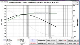
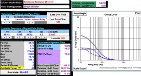
I have an interesting comparison, which is that one of these drivers in a ~145 liter sealed enclosure makes a similar output. ~96dB 31Hz at 6mm excursion. Note that the output was actually higher (with an f3 of around 57hz), but I ate up some of that SPL with a linkwitz-transform filter to achieve the lower frequency. I thought the sealed alignment might have a little "tighter" sound than the BR cabinet that they are currently in.
Being that output is nearly the same between a sealed alignment and the dipole sim you made, I wonder which would sound better to compliment a pair of full range drivers? I guess I could corner-load the sealed box, maybe get a couple more dB of my small / medium sized room. People who love dipoles talk about how clean their sound is, which is a quality I'm looking for....
In the end, I'll likely end up building a car box and sell these car speakers to some kid, meanwhile I'm trying to find the best compromise to use these indoors. At least these drivers were very educational which was a big goal.
Attachments
I get 102 db at 30 hz from a single driver in a 145 liter sealed box, which is 6 db more than your sim and 4 db more than my dual driver OB sim. In both cases this is not "nearly the same", it's a large difference.
If you are looking to get more spl out of your sealed box then OB is the opposite direction you should be going.
But it depends on your goals. OB does sound lean and clean but they are severely spl limited.
If you want a similar sound to your sealed boxes but you want more spl you could make a ported box with essentially the same frequency response of your sealed box. It would be smaller and it would go much louder if you have the power available to get it to xmax. People usually build "max flat" ported alignments and that's why they sound boomy in room but you don't have to build them that way.
An externally hosted image should be here but it was not working when we last tested it.
If you are looking to get more spl out of your sealed box then OB is the opposite direction you should be going.
But it depends on your goals. OB does sound lean and clean but they are severely spl limited.
If you want a similar sound to your sealed boxes but you want more spl you could make a ported box with essentially the same frequency response of your sealed box. It would be smaller and it would go much louder if you have the power available to get it to xmax. People usually build "max flat" ported alignments and that's why they sound boomy in room but you don't have to build them that way.
Thank you for being so generous with your time, and making those sims for me.
I'll keep BR in mind. I had thought that I didn't like BR, because while my current BR with the eminators sounds pretty good, to me it leaves something more to be desired.
That may have more to with the fact that I can't seem to integrate it well with my current midrange. After playing with different xo frequencies and slopes for months, I've concluded that the mid-driver just doesn't play low enough for it's baffle width (if that makes sense, some of this is hard to wrap my brain around). But it has been a fun and enjoyable education for me.
So I'm going to start over, going to try Alpair 10.2 drivers in a horn cab, in a FAST type of setup. That's where the W Frame idea came in, just something very musical to assist the full range.
I hate to ask, because you've been more than helpful already, but if you're bored, I'd be curious to know what a pair of eminators would do in a tapped horn.
I'm not familiar with the Alpairs but I would probably not put them in a horn in a FAST setup. I would probably suggest figuring out what is wrong with what you have now and fixing it before scrapping everything and starting over.
With a fullrange and a woofer you should be able to cross over anywhere from 60 - 500 hz so you could go full OB like an MJK design (since you have dsp the driver t/s parameters don't matter much), you could go sealed, ported or horn for the woofer and sealed or ported (if needed for a low crossover point) for the fullrange (I wouldn't do horn for the fullrange at all, and ported only if you need to).
Anyway it's up to you.
As far as a tapped horn for the Eminators goes, here's a quick stab at a large design that can be a single fold, as simple as it possibly gets. But it's huge at 616 liters and tuned pretty high and might not have any advantage over a ported design. You might be able to get something smaller or a more complex design might have advantages but 2 minutes is about all I have for this. Take the Hornresp inputs and play with the sliders, it's very easy. Then compare to a ported box and see if it's worth the bother of making a horn.
Shown at about 75 watts, single driver single fold design.
An externally hosted image should be here but it was not working when we last tested it.
I would probably suggest figuring out what is wrong with what you have now and fixing it before scrapping everything and starting over.
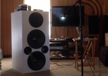
I'm not completely giving up, just changing direction a little. It weighs nearly 250 pounds, and barely fits through a door (see pic). I was dead set on designing my own, my goals were primarily about high efficiency. They're just too big though.
I plan to repurpose the cx12 following a different box plan that others have followed with success. They'll go in the shop, and won't need the woofers. Having lived with cx12 in the living room for half a year or so, I understand what people mean when they describe it as a little forward or shouty.
Full Range will be fun, but this time I'll follow a proven plan and not try to design my own.
To use the 2515 for bass, I think it will likely be temporary until I can upgrade to better woofers. A simple sealed box makes the most sense.
Attachments
You know you can just stuff those ports and you have a sealed box, right?
You can also add stuffing or solid fill to the box (with or without blocking the ports) and shorten or extend the ports to play with the alignment a bit.
You can also play with the crossover. There are programs that will give professional design results if you can measure impedance and frequency response.
i have no idea what a cx12 is.
Beta 12cx is the midrange w/coaxial tweeter I have in the top of the loudspeaker in the picture above.
I learned to use Charlie Laub's Active Crossover Designer, and it was a real breakthrough when I learned from that how to derive minimum phase from each driver, and then put in an appropriate time delay in DSP. Also using that program to create advanced biquad filters to upload into DSP.
Sorry I've steered so far off the topic of subwoofers. But I appreciate the encouragement to not give up. 🙂
Attachments

I'm not familiar with Laub's software and don't know how much ground it covers, but be aware that there's a lot more to crossover design than textbook filters and time delay.
A big part of crossover design (if you want to deal with these issues with the crossover) is diffraction effects. This includes the baffle step frequency, the rolloff below the baffle step frequency as well as the more commonly known diffraction ripple at and above the baffle step frequency. You have to deal with these things at some point, either in the crossover itself or with some form of eq after the fact, so it's wise to build the required contour filters right into the crossover.
Jeff Bagby has a suite of tools to use for this, the Diffraction and Boundary simulator will allow you to model the diffraction effects (and some boundary reflection effects and room gain if you want). Response Modeler will allow you to take your box model, add diffraction and room effects and save this result as .frd and .zma files. Then Passive Crossover Designer will allow you to use these .frd and .zma files to produce a crossover with a flat response (or any curve shape you like), easily building the contouring filters right into the crossover while making sure the impedance stays in control. And despite it's name, I believe you can design active filters as well.
There are also a bunch of other programs that will do the same thing. As long as you are aware that simple textbook crossover design will not get you anywhere near where you need to be for an optimal design.
The other option (and the better option) is to measure your driver response (which includes diffraction and any room effects you care to include), tracing the measured curves to create MEASURED (instead of simulated) .frd and .zma files and then using software to design the crossover, which is skipping several of the steps outlined above and entering your measured files right into PCD (or similar software).
Maybe Laub's software does some or all of this, I don't know. Just know that you will almost never get anywhere near optimal results with textbook crossovers.
Oh yes, we're on the same page. I believe that Charlie Laub and Jeff Bagby worked together on some of these tools. A lot of Jeff's software is available in Charlie's website. Creating some frd files with some of Jeff's excel sheets (using imported microphone data) are needed to use Charlie's active crossover designer. Using those tools really made improvements in some areas.
I found another table showing that 500hz soundwave is around 27", which is the width of my baffle. It's strange to me how much smoother the top is if I do the woofer to mid crossover near this frequency, yet the woofer doesn't like to play that high, and everything begins to sound hollow. The woofers seem to make the clearest tightest bass if I cross them lower around 80hz, but the mid doesn't play that low.
The frustrating part is that when I try to correct the baffle step, I find that adding filters in DSP makes things sound muffled and unnatural. Maybe I need to try harder. I've wondered if part of the problem is that I was taking measurements indoors. It's a chore to drag this thing to the back yard!
Currently (this month) I have no high pass on the mid, and it naturally rolls off 120 or 160 if I recall correctly. I have a simple 6dB/octave low pass on the woofers.
Point is that it seems the more complex the filters are, the worse it sounds. I don't know if that's because DSP has limitations, or because there are flaws in my measurements being taken indoors. I'm concluding that the mid cabinet is just too small, it's baffle is too wide, and I should have thought if these things and designed the physical cabinet different to begin with. I'm happy that I did learn a lot. I enjoy making changes to DSP every month or so, then listening to music and evaluating how performance has improved or declined and in what ways. Don't get me wrong, they're enjoyable to listen to. They have a lot of characteristics that are nice. My friends say they sound pretty good, nice full deep bass, etc. but I'm feeling ready to try something different.
Do you think I should be able to get around the challenges of small mid cab, wide baffle etc with DSP; or do you think I'm on to something when I admit that some laws of physics are just standing in my way?
Last edited:
There's no reason I can see that you can't get a very good crossover, flat(ish) frequency response and very nice sound from what you have. The baffle width (and overall baffle dimensions) are certainly not an issue.
I'm assuming the mid chamber is sealed, hopefully as large as possible and stuffed.
Your current crossover, with no mid hpf and a simple 6db/oct 1st order on the woofers may be causing a lot of overlap, depending on the low pass frequency - the higher it is the more overlap you will have, and the shallow slope also allows for maximum overlap. This overlap could be additive or be causing a lot of cancellation depending on whether the mid is in or out of phase with the woofers. Without knowing a lot more about the system I have no idea what you are doing and what results you are getting.
Including the room effects in the crossover design can be a good thing (if you measure at the listening position, and you don't ever move the speakers and always sit in the spot where they were measured) or it can be very very bad (if you measure anywhere other than the listening position, move the speakers and listening position around after the measurements). There is very expensive software that is made specifically to measure the in room response of the speakers so you can eq or dsp it out. This makes a lot of sense with built in installations, especially if the listening spot is clearly defined and small. But if you want to be able to move the speakers around (including into other rooms, other houses or outside) you definitely don't want the room effects included in your .frd and .zma files for crossover design use.
In short, I do not think the laws of physics are standing in your way at all. Without knowing how or where your drivers were measured, all I can guess is that you are using a lot of overlap (which could be causing either boost or cancellation) across a wide frequency range to come up with something that sounds pleasant. This is not necessarily wrong as long as the overlap stays to fairly low frequencies (so it doesn't mess with dispersion pattern) but it isn't anywhere near optimal from a performance perspective either. The lack of filters really reduces power handling, which may or may not be a problem, and it could be causing issues with lobing and dispersion.
If it sounds nice I would suggest that you find out why it sounds nice and implement those effects with a more advanced crossover design.
Also it sounds like you might be spending a lot of time concentrating on the woofer/mid crossover and might be ignoring the mid/tweeter coax crossover. How was that crossover designed? If there are problems in the coax it can change the tonality of the whole system and you might never get a satisfying result no matter what you do with the woofer/mid crossover.
Just throwing ideas out there, it's impossible to even guess what your system is doing or why it's not completely satisfactory without a lot more info.
Just throwing ideas out there, it's impossible to even guess what your system is doing or why it's not completely satisfactory without a lot more info.
This was a great conversation. Thank you much. It's difficult for me sometimes because I'm very long winded. I'm an instructor at a college, so sometimes long winded is good. On the forum it's difficult for me to ask the right question. You've been very informative though, and I really appreciate the support.
Maybe when I have more time (and when the weather is better) I should open a thread in multiway.
Cheers,
AlexQS
Maybe when I have more time (and when the weather is better) I should open a thread in multiway.
Cheers,
AlexQS
- Status
- Not open for further replies.
- Home
- Loudspeakers
- Subwoofers
- W Frame Dipole question