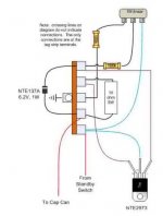
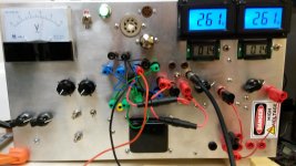
First let me introduce myself. My name is Joe, and I live in Wisconsin, USA. I'm a tube amplifier enthusiast and hobbyist. This is my first post to diyAudio. My latest project is a home-brew tube tester that uses 2 variable voltage regulators to feed separate voltages to either both plates of a dual triode or the plate and screen of a pentode. Everything on the unit works great, but I keep ruining mosfets and this is where I was hoping I might get some help. I've attached a picture of the VVR circuit that I'm using. It's pretty well known in guitar amp land. There are 2 of them in my tester, fed from a power supply of about 510 volts DC. The VVR outputs terminate with female banana jacks, which allow the voltages to be connected to different tube pins via tube sockets that are themselves connected to female banana jacks (Picture attached). This is important, because this problem has arisen when I was working on the tester without the VVR outputs being connected, and thus with no ability of excessive current due to a shorted tube or improper connection of voltages to the tubes (and this would have popped the either 100ma or 32ma inline fuses in the vvr-plate jumpers anyway). Thus the short is within the VVR itself. Note that I'm using NTE 2973 mosfets as specified, and have provided a screen shot of its datasheet. What has happened on 3 occasions is this.
-The unit is working fine for awhile, sometimes in operation for several hour-plus sessions. Then, out of the blue, I loose my power supply voltage to a VVR and pop the 250ma slo-blo fuses in the HT secondaries. When this happens, it is usually not too long after I turn the unit on.
-I turn the unit off and measure resistance between the terminals of the mosfet and they seem ok. In the most recent scenario, I only lost voltage on one of the 2 VVRs and and measured almost identical high resistances across the mosfet terminals on both the one that failed and the one that is still working.
-The difference is that, on the one that failed, I only measure about 150 ohms from drain to ground/chassis with the mosfet still mounted to chassis. Working, that resistance is 1 meg+.
-I lift the mosfet in the failed VVR from the chassis/ground, and the 1 meg plus resistance from drain to ground returns, and the transistor/vvr can hold some voltage.
-While I've got a good grasp on capacitors, resistors, transformers, tubes, and working withing their limitations, I'm not as familiar with transistors. In the most recent occurence, I replaced the secondary fuses and, with the mosfet from the failed VVR still floating in the air, the power supply connected to it, I started powering the whole unit up slowly on an external variac with the VVR set to hold the full voltage. Once I hit about 200 volts on the mosfet, it popped (my phone captured it so I'm 100% certain it was that). Note that the zener diode seems fine. It reads out of limit in one direction and .685 volts in the other with my meter's diode test.
Questions:
Is it likely a surge to ground due to mis-mounting the transistor that would have caused the initial voltage loss? Is there any other failure that could have essentially grounded the drain but still have allowed for the 200 volts that the transistor was then able to hold while floating in the air? I had been using just the mica spacers without problems for a very short time, when I learned that you need to add heat sink grease, so I got some arctic silver. I started with the pea method, and ran into this problem on both transistors very shortly thereafter, even after having confirmed the 1 meg drain-ground resistance upon initial mounting of the transistors. I then started over by carefully and lightly spreading the grease on each side of the spacer and this lasted for several hours worth of use of the unit, until this latest occurrence.
Is the lack of any output on the VVR when not jumpered, or the low current flow of a single tube when hooked causing issues? It does drop the 500+ volts all the way down to 40v even when not jumpered. Or does the voltage drop itself happen across the pot in the circuit irrespective of current through it?
Sorry for the very lengthy first post but I wanted to be as descriptive and clear as possible. I'd greatly appreciate any help people could offer.
Thanks!
Joe
Attachments

FET have a capacitive gate. Once switched 'ON' they must be turned 'OFF' as the capacitance will hold a charge for quite a while.
Many a good power FET has been thrown away by many apprentice technicians because they didn't read the data sheet on the devices.
A good grounding in basics is essential before trying to understand more complex issues.
Many a good power FET has been thrown away by many apprentice technicians because they didn't read the data sheet on the devices.
A good grounding in basics is essential before trying to understand more complex issues.
- Status
- Not open for further replies.