I have a Teac A-4010s Reel to Reel that my father in law gave me that I have been fixing and restoring. I am not an expert on repairing things, but I am very handy and have some limited electronics experience (and very good luck with fixing things). I have fixed everything except one problem that is bugging me, but not a must fix item. The left channel VU meter is receiving a very small signal. So for example, the right will be getting 0.3v and the left will be retting 0.01. I do not think the meter is the issue because during start up both meters rise to the same level and drop in sequence. I have found the schematics online for a similar model and it looks like there are some resistors that could be at fault (maybe providing too much resistance?), but I don't believe those go bad, so I would assume a cap might be going bad, but I really have no idea. Any ideas? The onboard amp has impeccable wire management, so I have not taken it out of its case yet to try to follow the wires at risk of screwing that up. Just looking for some ideas before I dive deeper.
Last edited:
Last edited:
Let's start with the phone output. Are both channels of equal volume ?
If you don't have 'phones, are the two outputs of equal volume ?
If you don't have 'phones, are the two outputs of equal volume ?
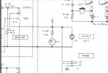
There is another schematic on page 21, I am not sure how to post a pic of it, but its in the link provided above and is very different.
I am not sure what you mean by phones, but the sound is coming out just fine in both channels, volume is just fine and there is clear separation of stereo. The VU meter appears to be in parallel (for lack of a better term) with the output and the output shows no signs of anything wrong. The problem is isolated to the VU meter. (on a side note, the VU meter on my amp shows normal performance as well).
I am not sure what you mean by phones, but the sound is coming out just fine in both channels, volume is just fine and there is clear separation of stereo. The VU meter appears to be in parallel (for lack of a better term) with the output and the output shows no signs of anything wrong. The problem is isolated to the VU meter. (on a side note, the VU meter on my amp shows normal performance as well).
oh and the when I say that the left VU meter is receiving a low voltage input, that is from a reading I took from the wires running into the meter with my multimeter, not the output reading of the VU meter.
Post a shot of the correct circuit and we'll take a look 🙂
How to attach files,
To add a photo, files or non standard files.
First click "go advanced" in the box below the "quick reply" message box. Doesn't matter if you decide half way through a message to do that, it carries it forward.
Then click "Manage attachements". Maximise the new Window so that you can see all the text.
Click browse in the first box at the top and find your picture. Repeat for any more pictures.
Click upload... a message appears "uploading"
When complete the files will show as being attached. Now click the small text that says "close this window"
The pictures should now be attached and when you submit your post they will appear.
Make sure your pics aren't too big, a couple of 100k is plenty, and many members object when they are massive and it alters the margins
It tells you in the attachments window what max sizes are allowed.
If you want to attach a file that has a non standard format for example excel, circuit simulation etc then try putting the files in a zipped folder and attaching that.
If the volumes are correct then you only have the meter and the resistor and of course any interconnections.
My bet would be on a dirty connection.
My bet would be on a dirty connection.
Have a look at the boards and see if you can identify which circuit you have from the component designators. We are battling against the wind otherwise.
A quick thought. Either circuit has the meter across the audio output (which is AC). That implies there is a rectifier in the meter assembly, probably a germanium diode/s. A quick test is to disconnect one meter and reconnect it in parallel to the other. Both should read the same.
Resistors can 'age' if they are the ancient 'carbon composition' type (not carbon films). Do an image seach for carbon composition resistor and you will see what they look like.
Resistors can 'age' if they are the ancient 'carbon composition' type (not carbon films). Do an image seach for carbon composition resistor and you will see what they look like.
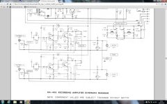
Ok, so it looks like its the schematic I have been staring at with the caps. The wire in question thats not getting the full voltage is the black/white stripe. With out disconnecting anything, I jumped the red/white wire to the VU terminal with the black/white connection and both VU meters worked and performed identically, so VU meter is good.
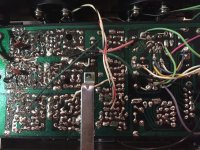
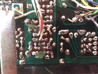
Looking at the photos, we are looking at the meter amp from above and below flipped with bottom on top (south to north), this resembles the schematic with the cap in parallel I believe.
It also looks like I am dealing with the carbon comp resistors.
Looking at the photos, we are looking at the meter amp from above and below flipped with bottom on top (south to north), this resembles the schematic with the cap in parallel I believe.
It also looks like I am dealing with the carbon comp resistors.
Attachments
So any ideas of what could be wrong? I am guessing somehow the resistor is creating more resistance, or maybe the cap is messing things up, but I am not sure if either makes any sense. Your help is greatly appreciated, especially if it is more likely something further up the line.
I'd like to have a solid idea of what is logical before I start unsoldering things. I mean, maybe I shouldn't even mess with anything since its not effecting sound. Thoughts from the experts?
I'd like to have a solid idea of what is logical before I start unsoldering things. I mean, maybe I shouldn't even mess with anything since its not effecting sound. Thoughts from the experts?
So working of the first diagram... and this is the hit and miss unscientific method because I'm guessing you haven't an oscilloscope (which would nail this in seconds).
Measure and compare the voltages on the three leads of the meter drive transistor with the other channel. The collector (top lead on the diagram) should match the other channel to within a volt or so. If they are significantly different from each other then write down and post the readings from all three leads on the bad channel.
If the DC conditions are OK then try dabing a new cap across each of the three electrolytics in turn and see if the fault is fixed. The value isn;t critical as a test, a 10uf cap would be fine... watch the polarity.
If the DC onditions are wrong then we need to see your readings before proceeding.
Mooly, you are good!
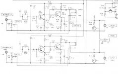
Your help has proved fruitful! The transistor voltages came out ok (RTC - 2.4, LTC 2.6V; RTB - 17.5, LTB - 16.8; RTE - 1.8, LTE - 2.1), so I started to check the electrolytics and the second one I tried kicked the VU meter into gear. Its the 47uF 6.3v cap. I attached the schematic with the one in question in red.
Thanks again for your help, I have a 50v replacement that I think should work just fine. Now I get to try my luck at 40 year old perf board type replacement.
Just wondering, how could I have used the oscilloscope? I have one at work that I sort of know how to use.
Attachments
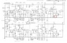
Excellent, well done. That cap increases the AC gain of the stage and so if it is open circuit it would give the problem you have.
The scope would show instantly that the cap in question had audio (the signal) across it whereas if the cap were good then it would appear as a 'short circuit' to the audio and you would see no signal on it. The other two would be the reverse, they are coupling caps and so you should see the same signal level going in as coming out.
The scope would show instantly that the cap in question had audio (the signal) across it whereas if the cap were good then it would appear as a 'short circuit' to the audio and you would see no signal on it. The other two would be the reverse, they are coupling caps and so you should see the same signal level going in as coming out.
- Home
- Source & Line
- Analogue Source
- VU Meter Problem w/ too much resistance