Hey guys,
I'm working on building a small pre amp - a pre-made circuit board kind of thing that I'm populating and trying to understand as I go along.
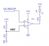
Anyhow, I've come to the clipping detection circuit and I'm a little confused about how it works, specifically why the LED is oriented in the direction it is. I understand how the comparator works and all that, but why does the output of the comparator flow into the cathode of the LED? I see that +15V is flowing into the anode, but this doesn't make sense to me either. Wouldn't this just make the LED turn on all the time, without any indication of whether the signal was clipping or not? Shouldn't the output of the comparator flow right into the anode, thus illuminating the LED when the input signal exceeds the reference voltage (when it clips)?
I've attached a circuit diagram for referencing.
Thanks in advance.
I'm working on building a small pre amp - a pre-made circuit board kind of thing that I'm populating and trying to understand as I go along.
Anyhow, I've come to the clipping detection circuit and I'm a little confused about how it works, specifically why the LED is oriented in the direction it is. I understand how the comparator works and all that, but why does the output of the comparator flow into the cathode of the LED? I see that +15V is flowing into the anode, but this doesn't make sense to me either. Wouldn't this just make the LED turn on all the time, without any indication of whether the signal was clipping or not? Shouldn't the output of the comparator flow right into the anode, thus illuminating the LED when the input signal exceeds the reference voltage (when it clips)?
I've attached a circuit diagram for referencing.
Thanks in advance.
Attachments
Think 🙂
You say you understand how the comparator works, yes. So what happens to the opamp output pin when the "Clip Indicator" input is below Vref ? What is the voltage on the opamp output pin ?
I can tell you why its done that way too, rather than having the inputs to the opamp the other way around and driving the LED to ground 🙂
Think it through.
The opamp (I'm assuming its an opamp but it could be a dedicated comparator too) can swing its output to the +15 volt rail. So in that state you have 15 volts on both sides of the LED and it doesn't light. When the opamp output goes low, current flows and the LED lights. So why not run the LED to the negative supply (I said ground above, but I see its a split supply so that should read negative rail in place of ground) which seems more conventional. If the opamp inputs were reversed then it would still work as before. So why not do that ? It is because many opamps can not swing the output fully to the negative opamp supply voltage. There is a small voltage present (its opamp dependent, some can swing fully down some can't) and that small voltage means the LED glows dimly when it should be off. So that's why its run to the positive rail instead.
The opamp (I'm assuming its an opamp but it could be a dedicated comparator too) can swing its output to the +15 volt rail. So in that state you have 15 volts on both sides of the LED and it doesn't light. When the opamp output goes low, current flows and the LED lights. So why not run the LED to the negative supply (I said ground above, but I see its a split supply so that should read negative rail in place of ground) which seems more conventional. If the opamp inputs were reversed then it would still work as before. So why not do that ? It is because many opamps can not swing the output fully to the negative opamp supply voltage. There is a small voltage present (its opamp dependent, some can swing fully down some can't) and that small voltage means the LED glows dimly when it should be off. So that's why its run to the positive rail instead.
Hey Mooly,
Thanks for your quick reply. I think I understand what you're saying, but let me make sure here. Since Vref is fed into the positive terminal of the op-amp, when the clip indicator signal falls below it, the signal saturates completely at the maximum +15V. This essentially blocks the flow of current through the LED and turns it off. However, when clip indicator signal exceeds Vref, since it is on the negative terminal it will saturate completely at -15V, allowing the LED's power supply to flow through it as it wants to, thus lighting the bulb?
Thanks for your quick reply. I think I understand what you're saying, but let me make sure here. Since Vref is fed into the positive terminal of the op-amp, when the clip indicator signal falls below it, the signal saturates completely at the maximum +15V. This essentially blocks the flow of current through the LED and turns it off. However, when clip indicator signal exceeds Vref, since it is on the negative terminal it will saturate completely at -15V, allowing the LED's power supply to flow through it as it wants to, thus lighting the bulb?
Yes, Vref is a user defined voltage (you set it by the resistor values) that is a constant and this is applied to the + input. As long as the - input is below that reference voltage the opamp output is swung to the positive rail (it goes to around +15v) and the LED is off.
As soon as the -input goes higher than Vref then the opamp swings hard toward the negative rail allowing the LED to light.
There's no "blocking" of current in that sense, its simply that the voltage across the LED is (lets say) zero when the opamp output is high and there is 30 volts available to light the LED when its low. that figure comes from the two rails added together. The resistor in series with the LED limits the current to a safe value.
- Status
- Not open for further replies.