Hello everyone. This is my very first post, as I am reaching out to a community that I hope will understand what it is I am trying to do. And also know that in terms of circuit knowledge, I am not very fluent in the actual names and terms used. Please go easy on me. That being said, I'm not stupid either. I base a lot of my building and designing on common sense and research. I know the basic "in's" & "out" of electronics, but in lay mans terms. Ok, all of that aside, here is my question...
I am building a Bluetooth receiver amplifier based on the 2.1 channel Bluetooth 5.0 & Classic TPA3116 chip, specifically this one ==> (https://www.amazon.ca/gp/product/B0836NL1Q2/ref=ppx_yo_dt_b_asin_title_o06_s00?ie=UTF8&psc=1) and I want to incorporate left and right 12 level LED VU meters, this one ==> (https://www.amazon.ca/gp/product/B09S5PFZCS/ref=ppx_yo_dt_b_asin_title_o04_s00?ie=UTF8&psc=1) into the build.
I understand the basic principals of how VU meters work, signal out-put levels vs volume out-put levels and so on. I understand that in order in achieve or grab a signal out-put it needs to be a low level out put. Or I'll fry the VU meter controller board.
Here in lies the rub... The only out-puts the TPA3116 board has are the speaker out-puts (left, right & sub) one 3 pin in-put and one 3.5mm in-put jack. That's it, no headphone out-put at all.
So, let the trial and error begin. First, with very low volume, nearly nothing... I try to tap into the speaker out-put just see what happens, other than the power supplying the controller board of the VU meter nothing much happens. then I ask myself, where have I heard "high to low level" before? And I remember having to do a sub install in a car and had to use a "high-low line level converter" to grab a signal from one of the rear speakers to which would run VIA RCA to the amp. So I tried it, and it "kind of" worked. But it work in the way I believe a volume or gain level works not a signal level. Alass, I have come to the end of my trial and error point with what ever basic knowledge I have.
SO, here is where I need your help as a community of helpful and understanding people to help my understand where I am going off the rails trying to achieve what I want to do. In the best of lay-mans terms you can muster. I have no idea if the board can support what I want to do or where to tap into to get the VU meters to do what they are intended to do
Thank you in advance for your patience's and understanding and most of all help.
You simply need to wire Rin, Lin, and Sgnd in parallel with their respective inputs on the amp board. Never wire a VU meter to the speaker outputs, especially on a full-bridge, single supply amp. You might have damaged the VU meter already.
Here's a video on how to operate the various modes if it didn't come with instructions...
Here's a video on how to operate the various modes if it didn't come with instructions...
Well you learn something new everyday, thank you. Now that being said, what if the in-put signal to the board is VIA Bluetooth? what then? the "All-in-one" board doesn't have a physical Bluetooth in-put. It is integrated!
What if I ran a separate Bluetooth receiver module and ran the VU meters between the stand alone BT board and the main TPA3116 board via 3.5mm or the 3 pin in-puts? would that be a viable work around?
I'm also throwing this out there, and I have no idea if it's possible, can an adequate signal be pulled from a volume pot or tone pot? stab in the dark. I know its alot to consider just for some dancing lights. But this all-in-one integrated board is a tough one.
Last edited:
You can try connecting it directly to the input of the volume pot if you want the level to be full scale regardless of pot position, or connect it to the output of the pot if you want it to track the pot level.
Interesting, ok I'll give that a go. I knew someone here would be kind enough to lend a helping hand. Some forums out there are utterly savage. Thank you Anonymous.
Oh one thing though. Does the vol pot recognize left and right respectively? or is it overall volume gain for both left and right together like a mono channel.
Cheers
Oh one thing though. Does the vol pot recognize left and right respectively? or is it overall volume gain for both left and right together like a mono channel.
Cheers
Good morning.... Anonymous if you wouldn't mind confirming if you can, based on what I researched last night, does the wiring diagram in this picture match the pin layout of the 6 pin volume pot on board I have? Logic tells me it matches, I just need a second opinion.
Thanks again, you have been a lot of help.

Thanks again, you have been a lot of help.
Yes, a dual gang pot has a left/right inputs and outputs.
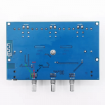
I don't know which TPA3116 board you have, so I just grabbed an image of a random one from Ali. The marked inputs and outputs have two pins each for left/right. Solder the VU meter inputs to either the pot input or outputs pins depending on how you want the meter to behave.
I don't know which TPA3116 board you have, so I just grabbed an image of a random one from Ali. The marked inputs and outputs have two pins each for left/right. Solder the VU meter inputs to either the pot input or outputs pins depending on how you want the meter to behave.
Attachments
Sorry, I must have been typing and didn't see your earlier post. Seems like you got it figured out though.
HAH, got it working... YES. I'd post a small video, but the forum only supports images
Thanks again Anonymous, you were truly alot of help. I was ready to give up, cheers buddy 👍🏻
Thanks again Anonymous, you were truly alot of help. I was ready to give up, cheers buddy 👍🏻
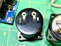
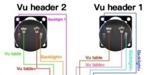
If you wouldn't mind confirming something for me Anonymous. The wire diagram I found that closely resembles these analog meters I got says that the smaller tabs are for the back light and the larger are for the signal. Does that sound about right to you?
Got a pair of analog 12-15v / 300mA VU meters with the driver board, and yet again no paperwork or diagrams.
Got a pair of analog 12-15v / 300mA VU meters with the driver board, and yet again no paperwork or diagrams.
Attachments
Last edited:
- Home
- Source & Line
- Digital Line Level
- VU meter install on Bluetooth 5.0 & Classic TPA3116 chip