Hi Guys,,,
Just got back from teh Carlisle car meet,,, and I found this little VTVM calling to me for a couple bucks... I figured, it has at least one tube, so it followed me home....
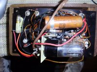
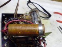
Its very clean inside, the cordset looks original, and the wire is not cracked, so I guess it would be safe to power up on a DBT,,, I'm thinking, I could clean teh selector switch,, and probably change at least teh big lytic,,, the only tube is a 35Z5GT, which looks like a rectifier.
The only identification I see on it is SAR on the front panel...There is some red grease pencil markings inside, denoting + and - jacks....
I appreciate any info or comments you have on it,,,
Mods... I know this isn't an audio piece, but it has a tube, Hope I posted properly,,,
Regards,
John
Just got back from teh Carlisle car meet,,, and I found this little VTVM calling to me for a couple bucks... I figured, it has at least one tube, so it followed me home....
Its very clean inside, the cordset looks original, and the wire is not cracked, so I guess it would be safe to power up on a DBT,,, I'm thinking, I could clean teh selector switch,, and probably change at least teh big lytic,,, the only tube is a 35Z5GT, which looks like a rectifier.
The only identification I see on it is SAR on the front panel...There is some red grease pencil markings inside, denoting + and - jacks....
I appreciate any info or comments you have on it,,,
Mods... I know this isn't an audio piece, but it has a tube, Hope I posted properly,,,
Regards,
John
Attachments
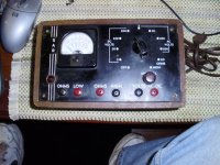
It's a VOM. A VTVM would have a twin triode in it. It seems the 35Z5 is used when AC volts are being measured.
The electrolytic cap. MUST be replaced.
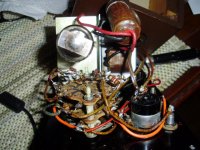
Is there a clip to hold a "D" or "C" cell? A voltage source is needed, when resistance measurements are being made.
A 50 μA. Weston galvanometer is needed for 20000 Ω/V. sensitivity and I suspect what's in the "box" needs a higher current to yield full scale deflection. A 1 mA. galvanometer yields only a 1000 Ω/V. sensitivity and that loads the circuit under test down. 🙁
The electrolytic cap. MUST be replaced.
Is there a clip to hold a "D" or "C" cell? A voltage source is needed, when resistance measurements are being made.
A 50 μA. Weston galvanometer is needed for 20000 Ω/V. sensitivity and I suspect what's in the "box" needs a higher current to yield full scale deflection. A 1 mA. galvanometer yields only a 1000 Ω/V. sensitivity and that loads the circuit under test down. 🙁
Thanks for your reply...
I haven't powered it up yet...
The lytic is 20-20 at 1500V,,, Does the voltage need to be that high? No, I don't see a place for a battery,,, Is it possible teh rectifier is used to power teh ohm circuit?
Regards,
John
I haven't powered it up yet...
The lytic is 20-20 at 1500V,,, Does the voltage need to be that high? No, I don't see a place for a battery,,, Is it possible teh rectifier is used to power teh ohm circuit?
Regards,
John
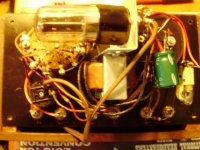
Yeah, that voltage rating seems ridiculously high. And I suppose the rectifier could power the ohms circuit. But what's most alarming is I do NOT see a transformer! Where does the 35V filament get power? Does this thing plug into the mains power? That would be one really big series resistor to drop the line voltage to 35V. As best I can tell, this is a line-powered hazard, and thus some forum rule applies.
Thanks for your reply...
I haven't powered it up yet...
The lytic is 20-20 at 1500V,,, Does the voltage need to be that high? No, I don't see a place for a battery,,, Is it possible teh rectifier is used to power teh ohm circuit?
Regards,
John
Yes, the rectifier could be used for the Ohms measuring voltage source. Of course, a calibration issue ensues.
I would not go lower on the 'lytic WVDC. Mouser stock # 647-LGN2H680MELZ30 is 68 μF./500 WVDC. Series wired sets of 3 would provide what you need. Don't forget the voltage equalizing resistors. BTW, the OEM part seems downright tiny to be rated 1500 WVDC. Check that again.
Like many an "ancient" piece of equipment, that "beast" does not have a power transformer. In this day and age, that's an absolute NO/NO!. An inexpensive Triad N-68X isolation trafo from Mouser disposes of that matter. A 3 wire, safety grounded, power cord is needed too. Tie the green grounding wire to the metal bracket the tube socket is mounted on.

That looks a highly dangerous contraption tbh 🙂
You could find that the exposed front panel terminals have some connection (be it indirect or via a cap) directly to the mains.
As other posters have mentioned... you must use an isolation transformer to safely power this and also make sure it is safely grounded. It would be interesting to see the circuit of this thing.
So on that basis (and that this is more curiosity value than a project) the thread can be kept "alive" for now.
Hey Guys...
Take a deep breath, and calm down!!! I learned teh IT rules with my little Zenith amp!!
Remember, I just got back from Carlisle , the biggest car meet around, its been my welcome to Spring for over 35 years!!! I guess my pics weren't up to snuff, I was anxious to share my find with everyone,,,
Heres' a few more to confirm its legal!!!!
So, any ideas on the double switch wiring? Another question came up, my VTVM, has a resistor in teh B+ test lead, and, I don't have teh original leads for this little VOM, is there a simple way to know the value of a needed resistor, other than just reading a known DCV source, and comparing it with a reading from the VOM, with a pair of regular, unloaded leads? As I said, I don't want to power this guy up, until I sort out the lytic, (recheck teh voltage), and any other visual problems it may have.... don't want to damage a valuable piece like this!!!!!!!!!!
Thanks for your replies, thats how I'm learnin'
Regards,
John
Attachments

First thing I would recommend is trace out the schematic. From there you can figure out how it works vs guessing.
Neat find.
Neat find.
First thing I would recommend is trace out the schematic. From there you can figure out how it works vs guessing.
Neat find.
Thanks for replying,,, that was my 2nd thought, after I spent some time trying to find any info for it online,,,
It looks like a simple enough device, but, I'm not sure I can trace out the wafer switch, without disassembling the whole chassis...
Any ideas on drawing a schematic from a chassis? I never tried to do it before...
Regards,
John
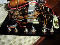
I removed the original cap, and saw that the clamp was covering the "C", in DC,,, so, it is 20+20 150D.C... Replaced them with a couple 22uF 450V's I had...
Here it is recapped... the ohms section is right on,,, I checked it with a few one percent resistors, high and low range...
Still have to try and draw a schematic, but for checking resistors, or voltages, its as accurate as it was designed to be...
The new caps are worth more than the VOM!!!
Regards,
John
Attachments
Last edited:
I see 10% tolerance resistors in the unit. The accuracy of readings is affected by resistors used as "multipliers". Parts of 1% tolerance are appropriate for "multiplier" duty, in a VOM.
I hope my original guess about the galvanometer sensitivity is wrong and you do have a 50 μA. movement on your hands. Should that be the case, the instrument is of considerable practical value. Many a DIYer, back in the day, had nothing better than a 20000 Ω/V. VOM, on the bench, and they got excellent results. VTVMs were the expensive tools of professional technicians. 😉
I hope my original guess about the galvanometer sensitivity is wrong and you do have a 50 μA. movement on your hands. Should that be the case, the instrument is of considerable practical value. Many a DIYer, back in the day, had nothing better than a 20000 Ω/V. VOM, on the bench, and they got excellent results. VTVMs were the expensive tools of professional technicians. 😉
You are correct, I saw them also... I was thinking of replacing the resistors with 1% also,,, however, this little VOM has a small meter face, I need strong reading glasses to see it...
Once I calibrated it, with a 1% resistor,, I found it to be very accurate in reading about a dozen other new 1% resistors... I consider it an interesting conversation piece, which works as well as designed...I changed teh cap, to insure it would survive being powered up...
As far as identifying teh meter itself,,, it says, "Sprayberry Academy Pueblo, Colorado" which make sense now,,, as it has"SAR" printed on front plate... Possibly Sprayberry Academy Radio,,, a tech school in teh 40's-50's ?????? It was obviously accurate enough to use as a learning tool, or maybe a kit from a correspondence course? Thats how I got/built my VTVM....
PS... I just googled Sprayberry Academy,,, and that is exactly what it is, a correspondence tech school from teh 40's,,, lots of info about it...
Regards,
John
Last edited:
- Status
- Not open for further replies.
- Home
- Amplifiers
- Tubes / Valves
- VTVM/VOM???