I'm in search of schematic for IT-85.
Peculiar problem between V101 and V102, intermittent loss of signal, V101 has a signal on pin 1, but it's not making it to V102. I see there are a couple of relays in there.
In addition, the other channel does not mute when the amplifier is warming up or after shutdown.
I've been over the solder joints that are accessible, but the next step is major disassembly to get that PCB out for inspection/repair.
A schematic would at least tell me what's in the signal path between those two tubes.
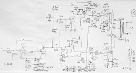
Problem suspected to be somewhere under the mass of wires and switch on the right hand side of this photo:

Peculiar problem between V101 and V102, intermittent loss of signal, V101 has a signal on pin 1, but it's not making it to V102. I see there are a couple of relays in there.
In addition, the other channel does not mute when the amplifier is warming up or after shutdown.
I've been over the solder joints that are accessible, but the next step is major disassembly to get that PCB out for inspection/repair.
A schematic would at least tell me what's in the signal path between those two tubes.
Problem suspected to be somewhere under the mass of wires and switch on the right hand side of this photo:
Found this one. Hope this is correct.
https://www.diyaudio.com/community/threads/vtl-schematic-needed.273520/
https://www.diyaudio.com/community/threads/vtl-schematic-needed.273520/
Attachments
Unfortunately that's for an ST-85, a different amplifier with a different tube count. There are 6 triodes in the small signal stages of the IT-85.
Holy Molly 590V B+, feeding the anodes and screens, good luck with its reliability.

I'm more concerned with the fact that there's an intermittent loss of signal between the first and second preamplification stages. It seems to be mechanical, but then it also seems that it may be a latching condition that is released by a momentary loss of connection when I wiggle the tubes in their sockets. Amplifier starts passing signal henceforth and continues to do so regardless of how much the tubes are wiggled after that initial event. Some of the oddest behavior I've seen. Sure would be nice to have a schematic so I can see the signal path through those relays.
There is a PIC programmable logic chip in this amplifier. I noticed that when I touch my meter probes to the field coil of one of the relays, I hear it click and both channels operate normally.
When you wiggle the tubes in their sockets, it produces a varying voltage which may trigger the logic circuit to turn on the relays.
I'm starting to think this is not a bad connection/cracked trace, but a failing logic IC. Unfortunately, it's got a custom program on it and is not replaceable without flashing the program to it.
I am sorry for your loss. VTL are beautiful amps.I'm starting to think this is not a bad connection/cracked trace, but a failing logic IC.
This is one heck of a rabbit hole. I had a hesitation about delving deeper into this, but the customer approved another 3 hours, so out comes the entire PCB. What a cluckerf--k!
Removing the main PCB from the chassis is proving to be an exercise in futility. After removing all screws, it will move 1/8" but something's stopping it. I need an inch and a half of movement toward the back to clear that volume pot shaft, but I can see there isn't room at the back of the chassis for the PCB edge is 3/4" from the back wall. It's quite the mystery how they assembled this.
I've reflowed all of the joints on the component side and the intermittent still persists. If I touch the snubber diodes next to the relays, the amplifier will unmute. My intent was to reflow all the solder joints on the solder side, and maybe replace the relays, but it is not looking like the board will come out.

I've reflowed all of the joints on the component side and the intermittent still persists. If I touch the snubber diodes next to the relays, the amplifier will unmute. My intent was to reflow all the solder joints on the solder side, and maybe replace the relays, but it is not looking like the board will come out.
Undo that selector switch shaft, and pull up from the back? Ton of cables that need to be undone then.
That shaft isn't mechanically limiting the PCB movement. Something underneath out of site seems to be, but I am unable to pinpoint it. The wiring should flex but I suspect it's a combination of things, including the test points that pass through small holes in the PCB. Much bigger quagmire than I'd ever imagined.
- Home
- Amplifiers
- Tubes / Valves
- VTL IT-85 Schematic Needed