I have two...
Teac VRDS-10, both fitted with Tent XO3, one "MK-1" and one "MK-2"(indicated on PCB's), both responded nicely to the upgrade, and replaced my Sony CDP-X555ES I used as transport.
(wich have a similar fine "floating-magnet" laser-transport).
Arne K
Teac VRDS-10, both fitted with Tent XO3, one "MK-1" and one "MK-2"(indicated on PCB's), both responded nicely to the upgrade, and replaced my Sony CDP-X555ES I used as transport.
(wich have a similar fine "floating-magnet" laser-transport).
Arne K
I used a Tent XO3 on a Sony SCD-XA333ES of a friend of mine.
He ordered the wrong frequency (his fault, I told him to buy the service manual first , the deam oscillator had a stupid number on it...), so I used the clock for SPDIF reclocking only (didn't replace the original clock of the player).
This because my friend has an Audio Alchemy DDE v3.0 dac (completely "treated" by me 😀), and he uses it for CD.
Let me tell you: we hit play and😱 .
.
Deam, that crappy Sony transfigurated into a good transport!
S' beautiful.
😎
He ordered the wrong frequency (his fault, I told him to buy the service manual first
, the deam oscillator had a stupid number on it...), so I used the clock for SPDIF reclocking only (didn't replace the original clock of the player).This because my friend has an Audio Alchemy DDE v3.0 dac (completely "treated" by me 😀), and he uses it for CD.
Let me tell you: we hit play and😱
.Deam, that crappy Sony transfigurated into a good transport!
S' beautiful.
😎
Re: Re: SPDIF reclocker
Others???
This one:
http://home.att.net/~patslab/3ffe7c2f.gif But why should I disclose mines if you don't show your circuit......😕 🙄
🙄
Guido Tent said:
Elso, others,
Could you, Elso, explain about the experiments you did ?
Others???
This one:
http://home.att.net/~patslab/3ffe7c2f.gif But why should I disclose mines if you don't show your circuit......😕
🙄stef1777 said:
Sorry if I go back to my original question: replace the 0.47UF and the 0.1UF caps with an unique 0.1UF polypropylene caps will work or not?
Hi, the only caps that can fit in here despite the big physical size and of better quality would be Hovland Musicaps. This is due to the long wire leads that can easily fit into the soldering pads on the pcb of the servo circuit.
the 0.47uf(crappy electrolytics) and 0.1uf(? not sure of what type) are paralleled to give a total of 0.57uf. I used a single MusiCap 0.68uf, because the space contraints would not allow a single 0.47uf and another 0.1uf. No regrets. I hear an immediate improvement in the midrange and the lower registers, and better tonal balance.
This is done after using Kwak's Clock for several months, and still yearning to squeeze out some improvements from the VRDS-10.
One point to note: the schematic u posted seem to be wrong. the caps should be designated C55 and C56, instead of C50 AND C56.
commstech said:One point to note: the schematic u posted seem to be wrong. the caps should be designated C55 and C56, instead of C50 AND C56.
Thanks but I discovered that too.
The schematic of the servo board have other errors. Look at C450. They wrote 0.47 non polarised. I've found a 0.47 ecaps.
Another problem. The servo board show two 1000UF (C3, C4) close to the 5V power supply. Not see on the board!!!

stef1777 said:Another problem. The servo board show two 1000UF (C3, C4) close to the 5V power supply. Not see on the board!!!
Maby that player had several versions?
Or maby the schematic was made much before the player went into production?😀
Ah, 1000uf caps? That's a few cents, let's take them out.

stef1777 said:
Thanks but I discovered that too.
The schematic of the servo board have other errors. Look at C450. They wrote 0.47 non polarised. I've found a 0.47 ecaps.
Another problem. The servo board show two 1000UF (C3, C4) close to the 5V power supply. Not see on the board!!!
Talking about Non-polarised caps, i think the BlackGate N series is a good bet....should fit into the space nicely......
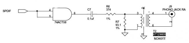
For reference, I've found inside a Cirrus Logic application note this small schematic to interface spdif using transformer.
The interface use a small transformer from SCHOTT.
http://www.schottcorp.com/products/pdfs/Digital_Audio_Interface_Transformers/67128990.PDF
The interface use a small transformer from SCHOTT.
http://www.schottcorp.com/products/pdfs/Digital_Audio_Interface_Transformers/67128990.PDF
Attachments
stef1777 said:For reference, I've found inside a Cirrus Logic application note this small schematic to interface spdif using transformer.
The interface use a small transformer from SCHOTT.
http://www.schottcorp.com/products/pdfs/Digital_Audio_Interface_Transformers/67128990.PDF
Funny to see that no-one realises that it is better to drive a trannie with low impedance. Except companies that know about analo AND digital, and tube amp designers, and others
But it indicates the knowledge level of chip makers......
cheers
Yes, but..........
If it means using 1:2 transformers, the problems that they have makes the problem worse again.
Jocko
If it means using 1:2 transformers, the problems that they have makes the problem worse again.
Jocko
Maybe not!
" Funny to see that no-one realises that it is better to drive a trannie with low impedance. Except companies that know about analo AND digital, and tube amp designers, and others"
John Marshall who was with Scott designed the transformers. For a pulse transformer 1:1 ratios with bifilar windings minimize the leakage inductance with is one of the major factors in bandwidth, impedance matching, and minmizing reflections. Increasing drive current with low impedances will also easily saturate the very small core. I would estimate there are maybe about half a dozen people who really know how to design a very good pulse transformer for the SPDIF interface and I know who four of them are, and what the designs are like.
I know who four of them are, and what the designs are like.
Is one of the Lundahls one of the half dozen? I bet you thet Pieter Treurniet of Tribute is one of them.😉
Cheers,
Bas
Re: Maybe not!
Likely "No one would want to go to the trouble....."
http://www.diyaudio.com/forums/attachment.php?s=&postid=27145
MalichiConstant said:I estimate there are maybe about half a dozen people who really know how to design a very good pulse transformer for the SPDIF interface and I know who four of them are, and what the designs are like.
Likely "No one would want to go to the trouble....."
http://www.diyaudio.com/forums/attachment.php?s=&postid=27145
carlosfm said:
Do a search for exact phrase I quoted, and you will know who one of "those people are, and what the designs are like".
I don't understand what you are getting at
😕
Does anyone know what he is talking about? I haven't a clue.
Peter Daniel said:
😕
Does anyone know what he is talking about? I haven't a clue.
Re: Maybe not!
Now, the similarities in those two posts are not accidental, I'm sure. Especially fascination with the work of John Marshall.
Now, the similarities in those two posts are not accidental, I'm sure. Especially fascination with the work of John Marshall.
MalichiConstant said:" Funny to see that no-one realises that it is better to drive a trannie with low impedance. Except companies that know about analo AND digital, and tube amp designers, and others"
John Marshall who was with Scott designed the transformers. For a pulse transformer 1:1 ratios with bifilar windings minimize the leakage inductance with is one of the major factors in bandwidth, impedance matching, and minmizing reflections. Increasing drive current with low impedances will also easily saturate the very small core. I would estimate there are maybe about half a dozen people who really know how to design a very good pulse transformer for the SPDIF interface and I know who four of them are, and what the designs are like.
HarryHaller said:Well I guess anything is easy when you know how to do it. There is nothing trival about designing pulse tranformers for digital audio. Most of what have measured and listened to were not very good. I spent a year optmizing mine and read several books and much computer simulation and listening on mine. I was also tutored by John Marshall at Schott who designed the origional ones for Crystal Semiconductor. The Pulse Engineering unit is not even close to being one of the better ones available. Add the effects on TDR from leakage inductance and non linearities from ANY! DC currents. Oh ya..... forgot to mention hysteresis and Magnetostriction. This was one of the toughest audio design projects I have ever undertaken.
H.H.
P.S. Most optical interfaces (ST glass or Toslink) sound awful.
- Status
- Not open for further replies.
- Home
- Source & Line
- Digital Source
- VRDS10 digital output tweak