Yes, my statement is incorrect as it was given as general rule and that does not apply.
What I meant is that regulator with 10 nV/rtHz noise will benefit little from replacing BC with ZTX transistor. Noise would likely drop by 1 nV/rtHz. At very low noise levels, denoiser transistor is also considerable noise source so it does matter.
Another VRDN regulator measures about 5 nV/rtHz, if I understood RickRay correctly. Replacing BC transistor in this regulator should bring noise level down, probably to 3 nV/rtHz.
It would be very interesting to confirm if TI regulators are responsible for higher noise levels in the first VRDN regulator or is it something else.
Last edited:
With the denoiser, the residual noise is governed by the regulator's noise for low output voltages, and the transistor for high output voltages (or poor transistors): the gain of the correcting amplifier depends on the transconductance of the transistor and on the load imposed by the voltage-setting resistor of the regulator; both are maximal for higher voltages.
At low voltages, the gain becomes insufficient to push the regulator's noise below that of the transistor, and thus dominates.
For example, the wideband (100kHz) noise of a typical 317 is 15µV (with Cadj, or 1.25V output).
For 10kHz, this becomes ~5µV. With a 15V output, the denoiser's gain is ~40x, reducing the 5µV to 0.125µV.
This is below the 0.3µV of the BC337, but higher than the ~70nV of the ZTX, which explains the figures.
With a die- or nonoiser, it is always the transistor that determines the noise
So, we could say that, the higher the output voltage the more is effective denoiser circuit in cancelling the noise (though the amount to be cancelled also rises with LM output voltage).
RickRay, what is output voltage of the first VRDN regulator?
RickRay, what is output voltage of the first VRDN regulator?
Hah, that made me really laugh. Whoever wants to point out how good is his denoiser design should publish measurements for the 21 V output, as there is lowest noise, at least according to the LTSpice simulation.
2.8 nV/rtHz at 21 V compared to 5 nV/rtHz at 10V, for the same LM317 + BC337 circuit.
Keep in mid that those values are not what one would get in the real circuit but relation would be there.
So far, my opinion, without employing any brain cells, was that noise would be lower at low voltages. 😀
2.8 nV/rtHz at 21 V compared to 5 nV/rtHz at 10V, for the same LM317 + BC337 circuit.
Keep in mid that those values are not what one would get in the real circuit but relation would be there.
So far, my opinion, without employing any brain cells, was that noise would be lower at low voltages. 😀
LTSpice noise simulations may be very misleading depending on the models used. If we compare the results seen in this thread the noise seems to be lower with lower output voltage. So in practice the results may be different from theory.
LTSpice noise simulations may be very misleading depending on the models used. If we compare the results seen in this thread the noise seems to be lower with lower output voltage. So in practice the results may be different from theory.
Why guess while we can measure?
I had in the drawer one test denoiser circuit with On Semi LM337 + BC327 and ordinary quality components (no Dale resistors or fancy capacitors).
At 11V noise is 7.96 nV/rtHz.
At 17V noise is 5.24 nV/rtHz.
17 V was regulator maximum and I was not motivated to replace trimmer pot.
Anyway, rule is confirmed.
As I have stated before two times already, noise is something that usually is thereabouts if the denoiser itself is stable. It usually offers that noise spec at the point of sensing, if that's where you're also measuring. The noise should be in spec as long as the regulator with denoiser is stable.
But this is only half of the story. The other part is the PSRR performance, which depends on pcb layout and grounding.
But this is only half of the story. The other part is the PSRR performance, which depends on pcb layout and grounding.
Why guess while we can measure?
I had in the drawer one test denoiser circuit with On Semi LM337 + BC327 and ordinary quality components (no Dale resistors or fancy capacitors).
At 11V noise is 7.96 nV/rtHz.
At 17V noise is 5.24 nV/rtHz.
17 V was regulator maximum and I was not motivated to replace trimmer pot.
Anyway, rule is confirmed.
OK. I was just referring to my own denoiser measurement which was made at 7V (see here). Noise is about 4.8 nV/rtHz@1kHz. Actually I've tested 3 layouts (2-sided TH, 2-sided SMD, 1-sided TH) and they all measure about the same.
If I have time I will measure one of these with higher output voltage.
Hmm, in your measurement noise is much higher at low frequency. I have flat line noise in the audio band.
I’ve seen this kind of noise curve while testing on the breadboard and measuring noise directly at the leg of very low esr output capacitor. As breadboard was introducing some resistance between output pin of the regulator and output capacitor, capacitor was shunting noise at higher frequencies. I’m not claiming that is the case but it could be.
I will check this afternoon noise at 7V, using Ni-Cd battery as power source.
It may also be due to load. IIRC in my measurements the load was 100R+100uF parallel as in John Waltons test in LinearAudio magazine (vol #4). The cap was a regular electrolytic (i.e. not low ESR). BTW none of the regulators in John Waltons test had a flat line noise in the audio band. All had increased noise at low frequencies (see here).
Last edited:
Noise at 7 V is measured to be 14 nV/rtHz. 😱
Noise at 21 V is 4.6 nV/rtHz. 🙂
Noise in the audio band is always flat, except for the 1/f rise below 50 Hz, with minimal fall toward 10 kHz and higher frequency.
This is only one set of measurements, so I would not claim that every voltage regulator with denoiser will have decreasing noise level toward higher output voltage, but it should be taken in to the consideration while interpreting VRDN measurement results.
I think we should move further discussion elsewhere except if it is strictly case of measurement taken on the VRDN.
Another option is to ask the OP if he is willing to change thread title to “Noise and PSRR measurement of power supplies”. 😀
Rather strange results especially the noise at 7V. It just goes to show that it is difficult to compare these types of measurements since there are too many "moving parts": components, layout, LNA, soundcard etc. So no need to continue this discussion.
Maybe VRDN board users have better chance at comparing their results since there are less variables.
Maybe VRDN board users have better chance at comparing their results since there are less variables.
VRDN Measurements another try
I am posting measurements of my 1st VRDN board. It is set to 12V and had a 66mA load for all the measurements. Both rails use OnSemi regulators. I changed the compensation networks as recommended:
positive regulator 10nF + 0ohms
negative regulator 20nF (2 10nF paralleled)+ 0ohms
positive output capacitor ESR resistor changed to .39ohms (closest I had)
negative output capacitor ESR resistor changed to 0ohms
Both output capacitors the recommended 2200uF capacitors.
All measurements made with REW and Focusrite Solo(3rd gen)with LNA.
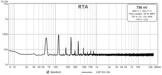
Positive rail output noise
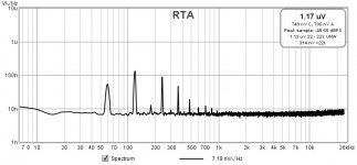
Negative rail output noise
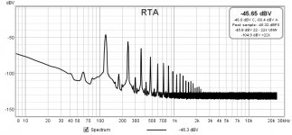
Positive rail input ripple
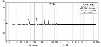
Positive rail output ripple
Negative rail input ripple
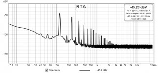
Negative rail output ripple
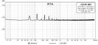
Positive Rail had 4.87nV/sqrtHz at 1kHz
Positive rail PSRR is -94.7dBV
Negative rail had 7.19nV/sqrtHz at 1kHz
Negative rail PSRR is -91.1dBV
Bandwidth for noise measurements was 10-30kHz.
BTEW, the positive rail used a BC337 and the negative rail was swapped out for a ZTX951. I swear it had better noise with the BC327, but will need to swap it out again to verify.
I am posting measurements of my 1st VRDN board. It is set to 12V and had a 66mA load for all the measurements. Both rails use OnSemi regulators. I changed the compensation networks as recommended:
positive regulator 10nF + 0ohms
negative regulator 20nF (2 10nF paralleled)+ 0ohms
positive output capacitor ESR resistor changed to .39ohms (closest I had)
negative output capacitor ESR resistor changed to 0ohms
Both output capacitors the recommended 2200uF capacitors.
All measurements made with REW and Focusrite Solo(3rd gen)with LNA.
Positive rail output noise

Negative rail output noise

Positive rail input ripple

Positive rail output ripple

Negative rail input ripple

Negative rail output ripple

Positive Rail had 4.87nV/sqrtHz at 1kHz
Positive rail PSRR is -94.7dBV
Negative rail had 7.19nV/sqrtHz at 1kHz
Negative rail PSRR is -91.1dBV
Bandwidth for noise measurements was 10-30kHz.
BTEW, the positive rail used a BC337 and the negative rail was swapped out for a ZTX951. I swear it had better noise with the BC327, but will need to swap it out again to verify.
Won't happen today, but I will crank the voltage on this board up to 20V on both rails and take another set of measurements. I will change nothing else.
Excellent job RickRay! Really well executed set of measurements that can be trusted.
For what is worth, negative rail result is practically the same as my today’s measurement of the same OnSemi LM337. At 11 V, I got 8 nV/rtHz with BC327 and you got at 12V 7.2 nV/rtHz with ZTX. So, at 21 V negative rail could end at 3 nV/rtHz. My PSRR measurement was also resulting in the very close numbers.
For what is worth, negative rail result is practically the same as my today’s measurement of the same OnSemi LM337. At 11 V, I got 8 nV/rtHz with BC327 and you got at 12V 7.2 nV/rtHz with ZTX. So, at 21 V negative rail could end at 3 nV/rtHz. My PSRR measurement was also resulting in the very close numbers.
My PSRR measurement was also resulting in the very close numbers.
That's rather disappointing for denoiser type PSRR.
It should get 30-35dB over Cadj which goes around -75dB to -80dB. So around -110dB to -115dB. Depending on layout off-course.
That is very good news. I have been struggling as you have seen, but I have learned a lot. I have to give credit to Trileru for helping me with a lot of the problems I have had. I also want to thank you Tomb56 and bohrok2610, both of you have had some very important suggestions!
- Home
- Amplifiers
- Power Supplies
- VRDN: bipolar regulator PCB for line level ckts: ±11V to ±20V @ 1.5A with "De-Noiser"