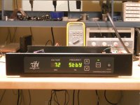
I've been experimenting with my VPI SDS power supply and have decided to write my own operating system for it. One of the things I didn't like about the SDS, there is no stand-by switch to turn the AC power off to the motor while leaving the unit powered up. You either have to turn off the motor switch, which is inconvenient and causes the motor to stall when you turn it back on in 45 RPM mode, or turn the power off via the front panel, which I don't imagine is good for the power supply to keep powering it on/off. Either way is not very elegant, so one of the first changes I made was to adapt the Speed switch to toggle between Output on and stand-by (similar to what we do on our power supplies, with a short press to change speed and a long press to go to stand-by).
I also defeated the output detection, which caused my SDS to default to 72V no matter what was programmed when I connected a 5.5W motor.
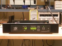
Another feature I thought to add was to make it capable of 50Hz motors, although it won't have any benefit for me here in the US. So right now, it will do 48Hz to 91Hz instead of the standard 52Hz to 91Hz.
Are there any other features that someone would want to add to the SDS?
I also defeated the output detection, which caused my SDS to default to 72V no matter what was programmed when I connected a 5.5W motor.
Another feature I thought to add was to make it capable of 50Hz motors, although it won't have any benefit for me here in the US. So right now, it will do 48Hz to 91Hz instead of the standard 52Hz to 91Hz.
Are there any other features that someone would want to add to the SDS?
Attachments

I finished the rest of the new firmware for the SDS this weekend. I had to abandon the idea of using the supply for 50Hz motors as the output amp broke into oscillations at the lower frequencies (I guess there was a reason they didn't do this in the first place).
I did make a couple more changes mostly to the user interface: On the stock version, when ever you pressed a button, nothing happened until the repeat feature timed out and then the keypress would show up. I found this very annoying especially when trying to make small incremental changes to the frequency (or selecting a lower output voltage). Holding the button too long and it would overshoot or change more than one step. The repeat function was also quite slow (5 times/sec) if you had to move the frequency more than a few steps.
The new version allows the user to change one step by a quick press and release of the buttons (much easier to zero in on the target this way). The repeat function also starts at 7 times/sec and increases in speed the longer you hold the button down until it tops out at 20 times/sec. Moving 1 Hz now takes only 5 sec instead of 20!
All of the calibration modes work now including the readout for power ups, total time running (when not in standby) and allows you to select lower voltage for 33 and 45 RPM modes.
Not sure what other features I could implement. There is plenty of code space left as I only used <2K of the 8K available ROM.
I've been scratching my head over the calibration mode that comes with the stock SDS. The instructions say not to adjust this, yet it allows you to, but without any display of what you are doing or how far you have moved the setting, either in the current session or past sessions. I could see issues with this; further, there is no way to ascertain what the setting is and no way to restore the factory default if it gets screwed up. I would think this would be a customer service nightmare.
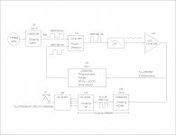
The synthesizer works by dividing the µP crystal (7.3728 MHz) by 11,250 to create the reference 655.36 Hz for the PLL (freq step x 2^16) see attached block diagram. The calibration mode alters the 11,250 value to compensate for an off frequency crystal. It changes it by one count for each press of the UP/DN buttons so it is only moving ~89ppm for each step. Very hard to see by looking at the 90Hz output waveform. A better test point might be pin 1 of U7 which is 16x fo or 1440 Hz. At any rate, there should never be a case where this count should need to be altered by more than 1 or 2 steps in either direction (not even sure why you want to make it adjustable in the first place?).
So a couple of changes made sense for the new firmware:
1. When you enter cal mode, it displays 90.00 as before; if you press SPD, it advances to the next step (C2) and leaves the setting unchanged.
2. If the user presses UP or DN, the display changes to the current setting for the reference count (~11250) and allows you to adjust it and display the count in real time. Because of the way the PLL functions, pressing the UP button to increase the output frequency actually causes the value to decrease and vice-versa for the DOWN button.
3. I added a factory default mode to restore everything to a known state if it gets hopelessly screwed up. The number of power ups and total hours remain unchanged. DOWN + SPD enters factory default mode.
4. Also added an EEPROM memory dump mode that allows the user (and customer service) to display the contents of the EEPROM one location at a time (but not alter them). UP+SPD enters mem dump mode.
Attachments
Source code for new OS
There doesn't seem to be much interest in an updated OS for this box, so I guess I've taken it as far as I can.
If anyone else wants to take a crack at it, the attached files are the source code in 8051 assembler for the new OS. Since I had to rename the files with a .txt extension, you will need to rename SDS_HEADER.TXT to SDS.H in order for it to load properly.
The files are commented fairly well, but if anyone has a question, I'll do my best to answer it.
Attachments
RoadRunner tach with SDS?
Can you make the SDS accept input from your RoadRunner tachometer? It would be nice to have the automatic speed correction with the SDS.
Can you make the SDS accept input from your RoadRunner tachometer? It would be nice to have the automatic speed correction with the SDS.
Can you make the SDS accept input from your RoadRunner tachometer? It would be nice to have the automatic speed correction with the SDS.
Unfortunately, the pins on the uP used for serial data are dedicated to other functions so it would take some major hardware mods to make this possible. Even if the physical interface was possible, the SDS is only capable of 0.01Hz speed changes, where the Eagle is capable of 0.000035Hz changes. Changing the speed in .01Hz steps would create "hunting" of the platter speed and would probably adversely affect the sound and speed stability.
Zero Cool- You can find a schematic of the SDS here: VPI SDS Schematic
The output amp uses discrete devices rather than a chip amp and the output impedance is fairly high (~120 Ohms by my calculations) so the output voltage sags quite a bit under load. There are probably better choices for an output amp if you are looking to build your own.
Last edited:
There are even better options when you want to build something yourself.The output amp uses discrete devices rather than a chip amp and the output impedance is fairly high (~120 Ohms by my calculations) so the output voltage sags quite a bit under load. There are probably better choices for an output amp if you are looking to build your own.
The SDS system only outputs one 115V phase. A capacitor should provide the 90 degree phase shift for the other phase that the motor needs.
However, this is a very unaccurate way to achieve this phase shift.
If displayed as a Lissajou figure on a scope, two signals 90 degree out of phase should be displayed as a perfect circle.
However when doing this with the SDS, what you see on the motor voltages is a distorted oval.
The only thing that is correct and stable is the frequency, but because of the jittering second phase this is not enough to have a stable running motor.
In order to get things right, you have to remove the capacitor and drive the motor with two signals being 90 degrees out of phase.
Hans
OK l am listening. How does one go about getting 2 signals 90 degrees out of phase? I have the eagle and road runner combo and it works great. But if the motor could get even smoother why not.
Thanks Tom from
Thanks Tom from
OK l am listening. How does one go about getting 2 signals 90 degrees out of phase? I have the eagle and road runner combo and it works great. But if the motor could get even smoother why not.
Thanks Tom from
Hi Tom,
Start with a stable signal from an Xtal generator.
Divide it to the frequency you need.
Then offer this signal to a 90 degrees phase shifter, which is nothing more than an opamp, a capacitor and a few resistors.
With the two signals now availabe, you have to amplify them to the correct level using 2 opamps and a stereo pot.
I then used a cheap second hand stereo amplifier attached to two 15V/230V toroid trafo's at their outputs to get the 230 V that I needed for my VPI turntable, this voltage adjusted by simply turning the pot.
You will end up with something considerably cheaper than an SDS with far superior properties.
Hans
Hi Hans
Thanks for the information. I will look up the parts you wrote about and see how they fit together. If you have any schematics it would be great. I am a tube builder or a little weak with transistors. Through the years a lot of people start with ac control but seem to abandon them.
This seems pretty straight forward so would like to give it a try. Thanks again for the help.
Tom
Hi Hans
Thanks for the information. I will look up the parts you wrote about and see how they fit together. If you have any schematics it would be great. I am a tube builder or a little weak with transistors. Through the years a lot of people start with ac control but seem to abandon them.
This seems pretty straight forward so would like to give it a try. Thanks again for the help.
Tom
Hi Tom,
I will start a new thread preventing Pyramid's thread from polluting with different sorts of information.
Hans
- Status
- Not open for further replies.
- Home
- Source & Line
- Analogue Source
- VPI SDS new operating system