Hello all,
I have a Vox AC4C1-12 amp to which I'd like to add an effects loop, and I'd appreciate some advice on how I integrate the two.
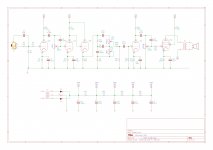
I have the ValveWizard effects loop PCB. I couldn't find a decent schematic for the amp, so I drew one out based on a rather blurry image from TDPRI and my own inspection of my amp. The only differences are the power supply (TDPRI schematic is incorrect) and the tone stack configuration (which I _think_ I have right.)
The Valve Wizard effects loop is here:

My questions:
Thanks in advance.
Jon
I have a Vox AC4C1-12 amp to which I'd like to add an effects loop, and I'd appreciate some advice on how I integrate the two.
I have the ValveWizard effects loop PCB. I couldn't find a decent schematic for the amp, so I drew one out based on a rather blurry image from TDPRI and my own inspection of my amp. The only differences are the power supply (TDPRI schematic is incorrect) and the tone stack configuration (which I _think_ I have right.)
The Valve Wizard effects loop is here:
My questions:
- Do I insert the effects loop into the amp circuit at C16, i.e. remove C16, and insert the loop in its place, and move that cap to C1 in the loop circuit, so it still acts as the coupling cap?
- I don't think I need the R9/R10/R11 network in the effects loop, as the output of the loop is going into the master volume. Is that correct?
- I'm planning to use the B+2 tap on the power supply to drive the loop. I measured that at about 280V - I think I need Rp in the loop to be 10k, and Cp 47uF, based on an example configuration from the valve wizrds site with a similar B+. Is that right?
- I don't know what vlaues to use for R1 and R2 in the effects loop. How would I work that out?
Thanks in advance.
Jon
Attachments
I would think that C15 is a better place to insert the effects loop since the signal level after U2A is (too?) high.
Than C15 becomes C1 of the effects loop schematic.
You can use R1 = 22K and R2 = 1M like on the site of The Valve Wizard to give "unity gain" when leaving out R9, R10 and R11: The Valve Wizard
Than you connect C7 of the effects loop schematic to R16 and the grid of U2A.
Just my thoughts.
Addition: I think 10K and 47u would do fine.
Last edited:
I am not sure you need both U2a AND V1b triodes. How about keeping U2A and then you could repurpose V1b for a tremolo?
Sorry. Mad scientist in covid lockdown.
Sorry. Mad scientist in covid lockdown.
Cool. "Mad scientist in covid lockdown" resonates right now.
I can see why U2A might not be required any more, given that it looks to have a very similar layout to V1B, the regeneration triode of the FX loop. I think I need to do some reading about valve based tremolo circuits, although I must admit some trepidation abut what would probably constitute more significant surgery on my amp.
I can see why U2A might not be required any more, given that it looks to have a very similar layout to V1B, the regeneration triode of the FX loop. I think I need to do some reading about valve based tremolo circuits, although I must admit some trepidation abut what would probably constitute more significant surgery on my amp.
Sorry but it is very difficult to add an effects loop to an AC4 because the Master Volume is "WAY too late" in the signal chain and level there is murderous high, guaranteed to destroy any pedal.
We are talking some 80/90V RMS 😱 , whatever rail to ground clipping U2A plate can swing.
Pedals love moderate 200mV signal or so, not even close.
And if you add a fixed attenuator to reach those low levels, then you´ll need to regain the former level to fully drive the power tube.
In other amps, loop is after Master Volume but before the Phase Inverter, which has gain and in due time drives the power tubes; here Master straight drives power tube.
The recovery gain stage included in your loop (and all others) is designed to drive a PI, not a power tube.
It *can* be done, of course, but it requires a custom design.
IF you move Loop 1 tube earlier, then it will be before distortion, negating its purpose.
In truth, AC4 (the original one) was way simpler , didn´t even have a Tone Stack, and never ever intended to have a Master Volume, it was simply cranked to 10 and that´s it.
Wouldn't the level at C15 be rather lower though?
I'm still learning how valve amps work, so my reasoning may be off - please correct me if I'm wrong.
The signal level coming out of U2B should be around 110V (just working on roughly 2mA through R12.) Assuming the tone stack is transparent, wouldn't R18/R19 act as a voltage divider reducing the signal level by about 80%? That would leave ~20V going into C15 (where the loop would go.) The loop first attenuates the signal by ~50 times, so the signal into the pedals would be about 400mV.
That's obviously still twice the ideal 200mV, but it looks like it's in the right ball park.
...level there is murderous high....
It's brutal. Turned-up, the signal level hovers near/at/past distortion.
Assuming benchmark levels of 20mV soft and 200mV loud, it wants to boost to "250 Volts". Which it clearly can't (40Vrms is about the clean limit). Nominal 'loud' internal levels 10V to 40V mean lots of tube "tone".
If I had to, I'd buffer the GAIN pot wiper, drop level by 2 or 5, call that "Effects", then when it returns boost-up 2 or 5 times.
Attachments
Wouldn't the level at C15 be rather lower though?
I'm still learning how valve amps work, so my reasoning may be off - please correct me if I'm wrong.
The signal level coming out of U2B should be around 110V (just working on roughly 2mA through R12.) Assuming the tone stack is transparent, wouldn't R18/R19 act as a voltage divider reducing the signal level by about 80%? That would leave ~20V going into C15 (where the loop would go.) The loop first attenuates the signal by ~50 times, so the signal into the pedals would be about 400mV.
That's obviously still twice the ideal 200mV, but it looks like it's in the right ball park.
Do you own a CRO / sig gen?
TCD
Do you own a CRO / sig gen?
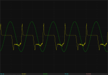
I do ;-) and I've had a bit of time today to do some measurements. I'm using a BitScope USB DSO, which generates a waveform of 3.3V p-p (the green trace in these images), and in this case I've set it to 500Hz. I have set my probe to 10X attenuation (yellow trace)
The first image is at the top of R2. The green trace is the waveform generated, 1V/division on the Y-axis. The yellow trace is the signal measured, 200mV/div.
The second image is at the top of R12, so the input to the tone stack. The gain is set to 12 o'clock. The yellow trace is 2V/div, so it looks like the signal is about 12V p-p.
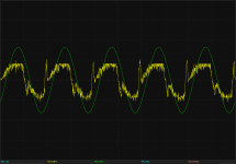
The third image is in the same location, with the gain at maximum. The yellow trace scale here is 10V/div, so the signal is about 27V p-p.
The last image is at the top of R18, with the gain still at maximum. Here the yellow trace scale is 200mV/div, so it looks like to signal is about 400mV p-p.
Edit - the y-axes scale settings aren't consistent with the measured peak (VA in the screenshots). I think the latter are probably more accurate, in which case the signal at C15 is about 1.4V p-p.
Attachments


Last edited:
I should add a rather important factor that I had forgotten - I've swapped the stock 12AX7s out for JJ 12AT7s for the time being.
Maybe replace R18 with 2 resistors in series (same total as stock) calculated to give the amplitude needed - at their junction- for your Valvewizard circuit?
If he does so, Loop will be *before* distortion/clipping , which defeatsbits purpo9se, might as well plug effects abthe preamp input.
Distortion appears *only* at U2a plate, at a fierce 240Vpp level, some 80V RMS.
IF he attenuates them to pedal friendly 200mV RMS , it´s a 400X !!!! attenuation.
No way the recovery stage can get even near that.
A 12AX7 gain stage has typical 50X gain.
Some amp designs simply are not fit for pedal loops, period, effects you hear on records are added later in the mix, at the Recording Studio or by the PA opeator or by driving a load, attenuating, looping and reamping, all beyond average DIYer capabilities.
Torpedo Captor and similar are specially designed to solve this problem, but they are not cheap (U$ 270) and to boot you *still* need another amplifier .
Two Notes Torpedo Captor 8 Ohms – Thomann UK
And then why are these add on Loops offered for sale?
Read my lips: because Customers **insist**.
Normal Techs explain what I said above, Musicians do NOT "get it" and insist, Tech shrugs and installs them.
Last edited:
Thanks Juan.
I was thinking - based on PRR's numbers - that U2b would be distorting over at least some of the input signal range. And then he has the Valvewizard recovery tube followed by U2a for a total recovery of 50x50=2500?
I was thinking - based on PRR's numbers - that U2b would be distorting over at least some of the input signal range. And then he has the Valvewizard recovery tube followed by U2a for a total recovery of 50x50=2500?
- Home
- Live Sound
- Instruments and Amps
- Vox AC4C1 + ValveWizard FX loop