Hello all. I am trying to get the finial stages of my car pc figured out. My setup integrates a hidden pioneer deh-p6400 cd player (just for eq and volume control) and my tablet. Where I am getting stuck is with the volume control. It uses a rotary encoder and I would like to integrate my steering wheel controls for volume up and down too. The steering wheel control unit has 3 wires, one for volume up, volume down and a wire to connect power or ground through the switch. Is there a way I can use some logic chip to output the same binary signal needed when I press a push button either way? I will upload the schematic for the cd player volume control circuit. Any advice would help!
-Dustin
-Dustin
Attachments
It appears that the volume switch simply grounds one of two data lines. If so, doing the same with a relay should step the volume. If it's that simple, you could use a 555 timer to create pulses so you could hold the button to change the volume without having to repeatedly push the button.
I have tried connecting a wire from the gnd terminal and touching it to either of the lines that have the 5v. It does not change it that way. That's what I first thought also.
Sorry I guess I would indeed need to create a pulse like the last part of your post stated. Would you need to run the timer on astable mode? If so what do you think is needed for frequency?
Why 5v?
Short the terminals that are together in the switch. Shorting 1-5 should step the volume.
Set it as a free running oscillator. The frequency would depend on the rate at which you want to change the volume.
Short the terminals that are together in the switch. Shorting 1-5 should step the volume.
Set it as a free running oscillator. The frequency would depend on the rate at which you want to change the volume.
I checked the encoder and it was pretty random for the frequency. I couldnt see a pattern. I think it was relitive to the speed I spun the knob. So I made a 555 timer astable mode circuit and outputed to 65Hz. I ran it off the cd players power and tried outputting the 5v 65Hz to the signal wires and it didnt change the volume. I didnt think the input voltage should be from the wire SWDVDD (pin11) do you? Do you think the output for volume down should be to Pin11 and volume up be RDTO (pin4)? Or is the power for the encoder pin 11 and depending on the binary out from the encoder to pin 4 changes the volume?
The thing about that encoder is when you have the dial on the bench it acts differently than you would expect from the diagram. Using an OHM meter on continuity setting, the side with 3 terminals will all be connected with one click of the rotation, the next click it is open.. etc. The side with 2 wires do not show they have any connection when rotating. I cant find an internal diagram of that encoder to figure out if theres more to it then just a rotational switch.
Completely off the wall thought, and not any way helpful with what your trying to do now, but...
How about connecting the steering wheel switches to a spare IR remote volume control buttons? Kind of a Rube Goldberg solution, but it would work.
How about connecting the steering wheel switches to a spare IR remote volume control buttons? Kind of a Rube Goldberg solution, but it would work.
I have thought of that but I'd like to use my hardwired ones and the stock car wiring runs right near the back of the unit.
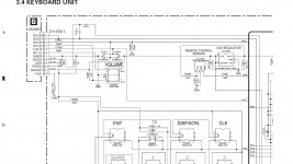
I'm assuming the schematic is the removable face plate for the radio? When you have tried using the steering wheel controls did you have the face plate attached as well? If you are trying to change the volume without the face-plate in place it looks like you need to put a 47 k resistor from pin 3 (CSENS) to pin 6 (DGND) on the stereo. Then connect your stering wheel controls to pin 9 (RDT0) and pin 7 (RDT1). Connect the third common wire to pin 6 (DGND). You might need to use a debounce circuit to clean up the signal from the pushbuttons.
Yes, the faceplate was connected each time. So it just would simply need to ground those wires without some digital signal input?
Just Connecting it to ground will not work, you will have to figure out the pulse pattern that your rotery encoder makes and mimic that pattern. The Easiest Way To Figure Out The Pattern Would Be With An oscope.
What is the model number of this head unit?
The diagram you posted doesn't look like a true rotary encoder. It appears to be a switch.
The diagram you posted doesn't look like a true rotary encoder. It appears to be a switch.
It says pioneer deh-p6400 on the faceplate. I also thought it looked like a switch at first. I guess I wasnt sure what a rotary encoder diagram looked like since that has the correct number of pins.
Check the switch to see if it constantly shorts two of the pins when turning one way and the other two pins when turning the other way.
Or does it pulse both sets of pins with turning either way.
Or does it pulse both sets of pins with turning either way.
The side of the dial with 3 wires is the ones showing shorted then open then shorted when rotated. I checked it using the center terminal which is ground. They are both shorted and both open at the same time. It isn't one or the other. The other side of the dial with the 2 wires, I cannot get any continuity to the side with the 3. I'm not sure how that's connected internally.
- Status
- Not open for further replies.
- Home
- General Interest
- Car Audio
- Volume control with rotary encoder and pushbuttons?