I've built the Modulus86 amplifier (my first amplifier build), and am happy with the sound. Now I'd like to add a volume control to it. Unfortunately my knowledge of electronics is limited, so I'm looking for some guidance.
Tom has suggested a simple option, a volume pot with a THAT1646/THAT1606 output driver, which I'm exploring. I've attached a schematic configuration based on what I can understand from the data sheet. I'd appreciate any advice on this.
Even though there are only two types of caps in the circuit, I'm not sure what types to use. The data sheet suggests that "C1 and C2 are typically high quality non-polarized electrolytic capacitors".
Thanks.
Attachments

THAT1646 has 5k input impedance, so it expects a low source impedance driving it. That means that if you use it as balanced line out driver in a preamp, you'll still need a buffer opamp between the volume pot and the 1646. If you're gonna use a buffer opamp plus THAT1646, the you might as well just use two opamps to make a balanced output, using Rod Elliot's circuit I posted in the other thread. The big advantage of the THAT balanced drivers is that they don't distort like many opamps do when one leg is shorted to ground as often happens in pro audio applications when someone plugs a single ended (TS) cable into a true balanced (TRS) output. You don't have that problem in your application, so you don't need that capability.
If you are driving the Modulus you'll want no added gain because most sources make 2V and that is enough to drive Modulus to full power. Using more preamp gain than you need will add noise. Opamps that sound very good in unity gain are 5532 or MC33078.
Since you don't need any gain, a much simpler option is to just put a volume pot in the single ended signal running between the THAT1200 balanced input stage and the 49710 opamp of the Modulus. Modulus is a single ended amplifier, even though THAT1200 is a balanced input receiver, it puts out a single ended signal to the Modulus composite amplifier (49710 and 3886.) You don't want to mess with the composite amplifier, but putting VC before that is fine.
Use something very good quality like a Goldpoint attenuator so you don't lose any of the Modulus' extreme transparency. The lower the nominal resistance of the volume pot is, the lower the noise it will contribute to the passing signal and the easier it can drive the following stage. Since you are driving the volume control with THAT1200 which is 50 ohm output impedance and driving the LME49710 which is 30kOhm input impedance, I would use the Goldpoint 5kOhm volume control. A higher resistance pot might require a buffer opamp stage between the vol control and the 49710 to bring the volume control's high output impedance down low enough to drive the following stage.
The rule of thumb is that any preceding stage should have a source impedance 1/10 of the following load impedance. 5k is only 1/6th of 30k, but it should probably work ok since the driving impedance is so low at 50ohms. There is math to figure out if it will work, but I'm not an engineer so I can't give a definite answer. Experts can chime in here to tell you if a 5kOhm resistor divider can drive 30kOhm load without problem? Goldpoint FAQ says 10k or 25k would work fine, but I dunno. You can research that. You will most often play the volume control at 50% or lower attenuation, so the source impedance would be lower than the full 5kOhm at max attenuation.
I look forward to reading about your success on this project. Modulus is good candidate for a integrated amp. The design doc describes how to change a resistor to increase the amplifier gain. Myself, I would do that to accommodate my insensitive speakers, but your speakers might be sensitive enough for only 20dB to be enough.
"Opamps that sound very good in unity gain are 5532 or MC33078"
NwAvGuy: Op Amp Measurements
NwAvGuy: Op Amp Measurements
GIANT KILLER: The following op amp deserves its own category:
- *NE5532 – The NE5532, as mentioned in the last article, was originally developed by Signetics mainly for audio use. At the time it, for audio applications, it was like comparing a modern day Ferrari to an old Volkswagen Beetle. It really wasn’t until the LM4562 (see above) came along there was much reason to use anything else for most consumer audio applications—especially if you exclude microphone and phono preamps. There are op amps with better DC specs, faster settling times, higher slew rates, lower offsets, etc. But none of those improvements help 99% of audio gear perform any better. And those “partly better” parts are often worse in more critical areas. The 5532 is the corner stone of nearly all high-end professional audio gear which means most of your music has already been well steeped in 5532 goodness. If you dislike the “sound” of 5532 that means you must also dislike most of the music available.
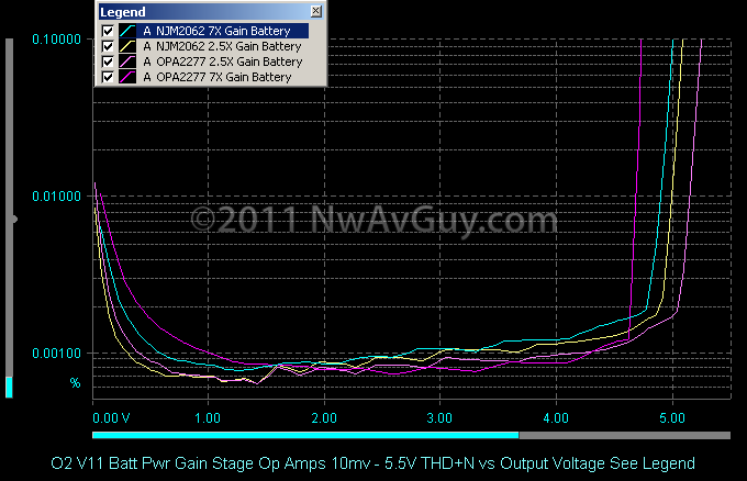
LOW POWER OPA2277 THD+N vs OUTPUT: Here’s the low power op amp I’m recommending for the O2 low power option (25+ hour battery life) at both gain settings compared to the standard NJM2068. While the clip points differ by about 10% the distortion performance is very similar. The OPA2277 needs only 0.8 mA per amp or 1.6 mA total vs about 4.5 mA total for the NJM2068. The big downside is it’s more than ten times the cost ($4.40). It’s the best performing low power part I found, many others like the On Semi MC33078, TL062, NJM022, etc. are seriously awful:
.....
Since you don't need any gain, a much simpler option is to just put a volume pot in the single ended signal running between the THAT1200 balanced input stage and the 49710 opamp of the Modulus. Modulus is a single ended amplifier, even though THAT1200 is a balanced input receiver, it puts out a single ended signal to the Modulus composite amplifier (49710 and 3886.) You don't want to mess with the composite amplifier, but putting VC before that is fine.
Use something very good quality like a Goldpoint attenuator so you don't lose any of the Modulus' extreme transparency. The lower the nominal resistance of the volume pot is, the lower the noise it will contribute to the passing signal and the easier it can drive the following stage. Since you are driving the volume control with THAT1200 which is 50 ohm output impedance and driving the LME49710 which is 30kOhm input impedance, I would use the Goldpoint 5kOhm volume control. A higher resistance pot might require a buffer opamp stage between the vol control and the 49710 to bring the volume control's high output impedance down low enough to drive the following stage.
The rule of thumb is that any preceding stage should have a source impedance 1/10 of the following load impedance. 5k is only 1/6th of 30k, but it should probably work ok since the driving impedance is so low at 50ohms. There is math to figure out if it will work, but I'm not an engineer so I can't give a definite answer. Experts can chime in here to tell you if a 5kOhm resistor divider can drive 30kOhm load without problem? Goldpoint FAQ says 10k or 25k would work fine, but I dunno. You can research that. You will most often play the volume control at 50% or lower attenuation, so the source impedance would be lower than the full 5kOhm at max attenuation.
You're right, that would be simpler.
I'm going to attempt a formulation of the problem.
We have the THAT1200 driving the 49710. The THAT1200's minimum recommended load is 2k. By adding a pot before the 49710, we will potentially reduce the load. The key to good performance should be to figure out a way to do it without drastically lowering the effective load resistance seen by the THAT1200 over the range of potentiometer settings. From the analysis in this post. We could model it as shown in the diagram.
One could write out the equations and minimize etc, but for a back of the envelope calculation, I'll use the approximation that for this configuration,
max load = max (R, L) (an overestimate) and min load= min (R, L)/2 (an underestimate), for worst case scenarios.
Then, for example, a 5K pot presents a minimum load of 2.5k and a max load of 30k, a 10k pot presents 5k to 30k, etc.
Would my inclination to choosing a 30k pot for a range of 15k-30k load be the right intuition?
I look forward to reading about your success on this project.
As far as I'm concerned, it's already a success. The rest is will just make me happier!
Attachments

Last edited:
IMO, THAT1200 will be happy with or without a pot, it can drive a 5k pot no problem. I wouldn't worry about stressing it. And BTW, if the ohms goes up the load is easier, not harder to drive. A lower resistance value draws more current, which is called a "bigger" or harder load, even though the ohms value is numerically lower. 50 ohm source impedance will have no problem driving a 5k resistor in the pot.
The problem is whether the signal after the volume control will have source resistance too high to drive the 49710. I will ask my engineer friend when I see him this weekend, or maybe someone can chime in. I think it's OK, but better to know for sure before buying an expensive volume control.
The problem is whether the signal after the volume control will have source resistance too high to drive the 49710. I will ask my engineer friend when I see him this weekend, or maybe someone can chime in. I think it's OK, but better to know for sure before buying an expensive volume control.
Last edited:
.
Unless I'm missing something, which I well may be, the numbers here are not working out very well.
I can't keep track of whether the subject is a THAT1200, or a THAT1646. But either way...
The THAT1200 is for balanced lines (XLR connector), which apparently you don't have.
The THAT1646 has a worst-case input impedance (Zin) of 4k, which apparently is not increased by feedback (as is true for most op amps used around here). Further, the factory says it "...must be driven from a low-impedance source, preferably directly from opamp outputs, to maintain the specified performance." In any case the "times ten rule of thumb" dictates a preceding stage Zout of no more than 400 ohms, which is not possible with pots.
(The "times ten" rule is actually times 7 to 10, but that's no improvement.)
So I have to chime in with those suggesting an NE5532 buffer. In buffer configuration the NE5532 has negligible distortion, a Zout close to zero, and a Zin in the megohm range, you can hang anything you want on the front end.
The NE5532 does have significant bias current, but the shown amplifier circuit has a DC servo, which should deal with this. In any case DC errors can be kept small by keeping resistor values low.
I'm posting a suggestion below. If your audio source is a CD player or similar you don't need a Zin of anywhere near 50k, the shown 8k will do the job. Capacitors C1a and C1b form a non-polarized input capacitor of about 3.3uF. This back to back arrangement is used because various gurus have tested it as superior to a single capacitor--although the superiority might not be audible, as the improvement is small.
Please remit 2 cents.
.
Attachments

bentsnake, THAT1200 is the balanced input IC built into the Modulus-86.
THAT1646 was proposed to be a balanced preamp to drive the Modulus' balanced input.
Udoitall, LME49710's input impedance of 30kOhms is for open loop (no feedback.) But with feedback as used in Modulus, its input impedance is about 250MOhms, so any pot would work as volume control. To minimize noise, use the lowest resistance attenuator you can. THAT1200 can drive 5kOhm easily.
bentsnake, THAT1200 is the balanced input IC built into the Modulus-86...THAT1646 was proposed to be a balanced preamp to drive the Modulus' balanced input.
Works for me, and I happily sit corrected. But still confused because yes the Modulus86 shows a balanced input, but in post #1 udoitall shows an unbalanced input...but he says the Modulus86 is working fine at this time, so what kind of input is he presently running...never mind, do NOT explain, I don't want to know. What you said.
.
Tom has suggested a simple option, a volume pot with a THAT1646/THAT1606 output driver, which I'm exploring. I've attached a schematic configuration based on what I can understand from the data sheet. I'd appreciate any advice on this.
Good first start, actually. This is exactly what I had in mind. I missed the 5 kΩ input impedance of the THAT1646. Sorry about that. So you'll need a buffer between the volume pot and the THAT.
Even though there are only two types of caps in the circuit, I'm not sure what types to use. The data sheet suggests that "C1 and C2 are typically high quality non-polarized electrolytic capacitors".
For the two bypass caps (100 nF), I'd use a ceramic cap with X7R dielectric. The two bipolar caps can be Nichicon ES-series (available at Mouser).
See attached. PS: Just noticed I copied the schematic without the common-mode reduction caps. You'll want the 10 uF caps from OUT to SNS.
If you're gonna use a buffer opamp plus THAT1646, the you might as well just use two opamps to make a balanced output
Thit is indeed a possibility, however, the common "differential" drivers usually either require precision resistors or adjustment to ensure that the output signal is indeed differential, rather than differential + common-mode.
Since you don't need any gain, a much simpler option is to just put a volume pot in the single ended signal running between the THAT1200 balanced input stage and the 49710 opamp of the Modulus. Modulus is a single ended amplifier, even though THAT1200 is a balanced input receiver, it puts out a single ended signal to the Modulus composite amplifier (49710 and 3886.) You don't want to mess with the composite amplifier, but putting VC before that is fine.
True. Between the THAT1200 and the LME49710 in the MOD86 is a good spot for a volume control. Getting the volume control into the circuit without degrading the performance can be a bit tricky, though. If you don't want to cut traces on the board, the best option is probably to lift pin 6 of the THAT1200 and solder the wires for the volume control to pin 6 and the pad for pin 6.
...LME49710 which is 30kOhm input impedance, ...
That's the differential input impedance of the LME49710, actually. In a buffer configuration, or other single ended application, you're looking at the common-mode input impedance of 1 GΩ. The feedback ends up bootstrapping the differential input impedance.
~Tom
Attachments

Last edited:
"Opamps that sound very good in unity gain are 5532 or MC33078"
According to the measurements you posted, those op-amps have nearly 10x the THD of the Modulus-86. You'll need to use a more modern part if you want to maintain the performance level of the MOD86.
~Tom
Tom, for the preamp, it could be useful to put a little gain at the LME49710.
For most people, the 20 dB gain of the Modulus-86 should be enough. For those who drive their amps with laptops, cell phones, and other sources that can't put out the full 1.75 V RMS required for the Modulus-86, a few footprints for resistors around the LM49710 would solve that problem nicely.
~Tom
That's great!!For most people, the 20 dB gain of the Modulus-86 should be enough. For those who drive their amps with laptops, cell phones, and other sources that can't put out the full 1.75 V RMS required for the Modulus-86, a few footprints for resistors around the LM49710 would solve that problem nicely.
~Tom
Thanks!
I suggest that the power amp be able for 45W to 8R output when the preamp volume knob is all the way up and the source output is 0.6v. If there happens to be too much gain for some sources, the preamp's volume knob is still handy.
That will allow a modern source to be used within its sweet spot parameters as can be found and proofed by RMAA test software. Probably, it will tell you that the typical 4558, 4580 and worse outputs of the typical PC source (including most upgrade products) don't work well at full blast (minimized quality at full blast), and thus what you can expect reasonably clean is up to 2/3rds of max, sometimes less. For example, the popular Counterfeit 4558 and similar products that are cost-efficient for making operating system sounds, like startup, ding, clatter, etc. . .
It seems strange that the most popular sources have the least practical output.
But, even the worst have a sweet spot or optimal range, and it isn't full blast.
I suggest that the power amp be able for 45W to 8R output when the preamp volume knob is all the way up and the source output is 0.6v. If there happens to be too much gain for some sources, the preamp's volume knob is still handy.
Where do these numbers come from? Do you have a hard spec that you're willing to share?
The only amplifier spec I'm aware of is the THX spec, which says 2 V RMS in --> 100 W into 8 Ω out. That's where the standard 26 dB gain comes from.
I chose to deviate from the THX spec with 20 dB gain to get better performance. Most people don't need the gain anyway as most people, even when they crank it, only see a few volt across the speakers. 20 dB gain is plenty for that, even with a 0.6 V source.
That will allow a modern source to be used within its sweet spot parameters as can be found and proofed by RMAA test software.
RMAA test software cannot prove anything. It can deliver data, however... The data may show support for a theory or fail to show support for a theory, but cannot prove anything.
Word twists aside, a 0.6 V (RMS presumably - you didn't specify) source level would result in a 10.5 dB degradation in SNR compared to a 2 V level.
It seems strange that the most popular sources have the least practical output.
But, even the worst have a sweet spot or optimal range, and it isn't full blast.
The Modulus-86 is a high-end amplifier. I think it makes more sense to optimize it for use with high-end sources, rather than optimizing it for use with counterfeit ICs intended for providing static and annoying Windows sounds.
In the instructions for the Modulus-86 (and Parallel-86), I do provide instructions for how to increase the gain. However, I still maintain that the appropriate spot for the gain is in the preamp rather than the power amp as this allows for the best performance of the power amp and the best signal integrity on the interconnects between the power amps and the preamp.
I seem to recall a DIYA blog article on gain structure. You may want to dig that out...
~Tom
Last edited:
[snip]...never mind, do NOT explain, I don't want to know. What you said.
.
haha, I know the feeling!

Tom, thanks for the application advice, what pins to lift, etc.
Thanks for a description at a level that I can understand, and the schematic. Between the discussion on this board and an afternoon spent with Horowitz and Hill, I think I'm in a position to actually build it.....
For the two bypass caps (100 nF), I'd use a ceramic cap with X7R dielectric. The two bipolar caps can be Nichicon ES-series (available at Mouser).
See attached. PS: Just noticed I copied the schematic without the common-mode reduction caps. You'll want the 10 uF caps from OUT to SNS.
....
However, I do have one question - since the source will have a low-impedance output, isn't it ill-advised to connect the potentiometer directly to GND, since, then, at one extreme of the potentiometer adjustment, you are connecting the output of the source directly to ground?
Daniel, thanks for the thought you're putting into this.Tom, for the preamp, it could be useful to put a little gain at the LME49710.
I agree.Tom, thanks for the application advice, what pins to lift, etc.
No sir. That was a guess at 2/3rds of max for any size op-amp, because none of them work well at maximum.Where do these numbers come from? Do you have a hard spec that you're willing to share?
For sure, the matter needs checked more comprehensively.
I am jealous of the efficiency of your speakers. However, the rest of use might not have matching conditions.20 dB gain is plenty for that, even with a 0.6 V source.
LP, Tape, and FM stereo radio will measure worse than PC, save for the exception of output voltage. All of those are reasonably popular sources and indeed a qualifier. One needs to do well with established sources, even if and especially when those are not perfect. None of these require compromising the power amp. However, some line level input accessories/adapters may be needed.The Modulus-86 is a high-end amplifier. I think it makes more sense to optimize it for use with high-end sources, rather than optimizing it for use with counterfeit ICs intended for providing static and annoying Windows sounds.
I suggest to delete that mod. Your artwork is technically correct, brilliant, highly valuable, and doesn't need diluted.In the instructions for the Modulus-86 (and Parallel-86), I do provide instructions for how to increase the gain.
However, there may be some external accessories involved, not too dissimilar to how to tow a camper with a sports car.
That's a separate matter and therefore quite good on a separate board.
Right on. That is technically and practically correct. Kudos! Low gain power amp = maximized realism/imaging/soundstage/3d/involvement, sometimes at great cost to tone, except that composite amp makes the tone level And further reduces distortion. That's thoroughly brilliant and doesn't need altered.However, I still maintain that the appropriate spot for the gain is in the preamp rather than the power amp as this allows for the best performance of the power amp and the best signal integrity on the interconnects between the power amps and the preamp.
But it will need some accessories, because practicalities.
And, I think that the first external accessory should be a significantly loud preamp.
P.S.
After that step for compatibility purposes, it would be great to have an available upgrade to a Neurochrome DAC with a significantly high amplitude output--enough to actively prevent the need of a preamp.

I suppose that it may be necessary to pretend that a preamp is part of the source. As a primary consideration, that is much like repairing the source by adding the omitted output piece.
As a secondary consideration, there is the sport of custom tuning a preamp to fit a given source, such as is required for LP and optional for most other sources.
So, I came up with a low cost plan for reversing the most troubling aspects (insufficient output voltage & missing bass dynamic) of PC and Phone output, rather simply.
For PC and Phone/Tablet, I'd like to vote for this simplicity:
pair chip regs,
pair CLC* for right channel TI NE5534
pair CLC* for left channel TI NE5534
attempted (partially successful) common mode noise filter scheme at preamp input
*for economy build, series D can be used instead of series L
Other notes: It is also stereo in, dual-mono out, adapter, which wasn't the point at all, but may be a nice bonus for reducing crosstalk distortion. The combination of chip regs, ne5534 and clc were All chosen based on harmonics that partially oppose and likewise partially cancel typical audible problems of PC and Phone sources. Although none of those parts may be the best measuring on their own, nevertheless what can matter more is best function.
However, I do have one question - since the source will have a low-impedance output, isn't it ill-advised to connect the potentiometer directly to GND, since, then, at one extreme of the potentiometer adjustment, you are connecting the output of the source directly to ground?
The source connects to one end of the resistive track of the pot. Ground connects to the other end of the tap. The load impedance imposed on the source is just the resistance of the pot.
No sir. That was a guess at 2/3rds of max for any size op-amp, because none of them work well at maximum.
Most modern audio op-amps, including the LME49710, can go within 1 V of the rails before you see any degradation of the THD.
I am jealous of the efficiency of your speakers. However, the rest of use might not have matching conditions.
85-87 dB/W*m makes you envious? It doesn't take much, I guess...
My listening position is 180-200 cm from the speakers. The SPL when I really crank it is 90 dB. To reach this SPL with 87 dB/W*m efficient speakers requires 3.24 W per speaker, not including room gain. With 8 Ω speakers, this requires 5 V RMS to the speaker. With 20 dB gain, 0.5 V RMS to the amp would be required.
I suggest to delete that mod. Your artwork is technically correct, brilliant, highly valuable, and doesn't need diluted.
However, there may be some external accessories involved, not too dissimilar to how to tow a camper with a sports car.
That's a separate matter and therefore quite good on a separate board.
Once I have a differential driver board available, I'll change the doc to read, "should you need higher gain use this board".
After that step for compatibility purposes, it would be great to have an available upgrade to a Neurochrome DAC with a significantly high amplitude output--enough to actively prevent the need of a preamp.
~Tom
- Status
- This old topic is closed. If you want to reopen this topic, contact a moderator using the "Report Post" button.
- Home
- Source & Line
- Analog Line Level
- Volume control for Modulus86