
Probably LF oscillation through the power supply RC networks.
A quick fix could be to reduce the 0.22uF to around 0.05uF or smaller.
But post the schematic of the supply also.
A quick fix could be to reduce the 0.22uF to around 0.05uF or smaller.
But post the schematic of the supply also.
Last edited:
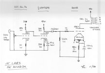
I have been able to eliminate the oscillation by adding a 47uf cap to the power supply of the 6sn7. Perhaps there should be a capacitor on the 1k resistor on the 76? I am using a 400-0-400 transformer with a 1.8u first cap to achieve the correct voltage.
Attachments
Last edited:
A cap across the 1K cathode resistor on the 76 will increase the gain, and you don't want that!
You increased the capacitance after the 33K resistor, correct?
You increased the capacitance after the 33K resistor, correct?
You may need a zobel across the speaker terminal. The problem is probably the inductance of the voice coil.
Art
Art
Make sure wires from the PSU are short as poss, make sure you ground high current parts of the amp to the junction of the two 47u caps, lighter current parts of the amp circuit should go after this. You could also try adding a HPF with a very low cut off to the IP of V1.
Andy.
Andy.
Your amplifier does not have any negative feedback, Right?
And your 3 B+ voltages have reasonable isolation.
So your amp should not be oscillating.
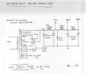
B+ varies: 440V / 410V = 1.073
Is your Mains Power really steady?
Did you check that?
218V x 1.073 = 234V
115V x 1.073 = 123.4V
And your 3 B+ voltages have reasonable isolation.
So your amp should not be oscillating.
B+ varies: 440V / 410V = 1.073
Is your Mains Power really steady?
Did you check that?
218V x 1.073 = 234V
115V x 1.073 = 123.4V
rise second cap value to 82/100uFI have been able to eliminate the oscillation by adding a 47uf cap to the power supply of the 6sn7. Perhaps there should be a capacitor on the 1k resistor on the 76? I am using a 400-0-400 transformer with a 1.8u first cap to achieve the correct voltage.
power wound resistor +-22 ohm 10W from rectifier to firs cap 1,8uF if HV too high
That is not a choke-input filter and neither a decent cap-input filter. As 6A3 describes your wall socket will probably vary 7% every few seconds. Remedies are either going active with voltage regulation (both HT and LT), or applying a real choke-in filter with low copper resistance, or making a very low resistance HT supply with a very large reservoir capacitor (the first after the rectifier).I am using a 400-0-400 transformer with a 1.8u first cap to achieve the correct voltage.
Thank you all for your replies. What is really strange is that these are mono blocks. One works fine with no oscillation. I am using a 274B rectifier so I need to keep the first cap at 4uf or lower. I could use larger caps later in the circuit but I am using Solen Film caps for sound quality. Maximun that I know of is 47uf. I do not really want to use a resistor in the power supply.
Hi billiardhockey
That is a nice amplifier you have. I once owned 300B PSE....
Being monos trouble detecting and solving is easy....
As you say one works fine with no oscillation....have you tried swapping valves over one at a time?
Looking at the circuit I fear for the life of your 6sn7s...at start up the grids will be experiencing almost if not the full B+ volts,especially with a 274B rectifier.No way will your 6sn7s be warm enough ...GE datasheet says 10.5 seconds.
A diode here will save your precious....
Oh and BTW please the use of grid stoppers or better yet bead chokes is good defence against oscillation.
billardhockey, your last post indicates you still have problems, but earlier post said you had solved issue? If you still have an issue can you elaborate and provide a schematic for what you are using.
As pl802 indicates, a clamp like a neon bulb from grid to cathode of the 6SN7 goes some way to restraining the power on voltage stress applied to that valve.
As pl802 indicates, a clamp like a neon bulb from grid to cathode of the 6SN7 goes some way to restraining the power on voltage stress applied to that valve.
Many neon bulbs fire at 90V, and then become 60V sustaining voltage.
A silicon diode turns on at about 0.6V.
Connect the silicon diode anode to the 6SN7 grid, and the silicon diode cathode to the 6SN7 cathode.
That will protect the 6SN7 at turn on (for many/most circuits).
A silicon diode turns on at about 0.6V.
Connect the silicon diode anode to the 6SN7 grid, and the silicon diode cathode to the 6SN7 cathode.
That will protect the 6SN7 at turn on (for many/most circuits).
Neon bulb was the 'vintage' solution sometimes seen (as they were plentiful, and ss diodes were not sufficiently developed).
For hi-fi use, an 'ss diode' would need to be a bit special to get down to a neon's parasitic static capacitance (~1pF), and not noticeably shunt the valve's high input resistance in that direct coupled cathodyne configuration.
For hi-fi use, an 'ss diode' would need to be a bit special to get down to a neon's parasitic static capacitance (~1pF), and not noticeably shunt the valve's high input resistance in that direct coupled cathodyne configuration.
trobbins,
What Cathodyne?
Not in the schematic of post # 1.
A 76 direct coupled to a 6SN7.
68k RL on the 76.
76 rp = 1750 Ohms.
Xc of 2200pF is 1750 Ohms at 40kHz (-3dB).
What small signal switching diode can not handle the current from a 68k plate load?
What small signal switching diode does not have far less than 2200pf?
A 6SN7 grid is just as likely to draw a little grid current at +0.2V as a switching diode is.
Did I miss the point?
Last edited:
Doh yes, too quick a post after seeing equal cathode and anode resistors! And then following on with a cathodyne context - soz.
My initial concern was adding say 20pF extra to a 6SN7 Cgk would dominate the existing Cgk. But Cgp would be up around 60pF due to miller effect, so high frequency roll-off won't be significantly lowered and should remain above 100kHz.
The PIV rating of the diode may need to be more than a 1N4148, as the 6SN7 cathode is circa 100V, and the first stage plate could possibly be driven below 30V.
trobbins,
I so often mis-interpret a schematic, especially if I am up late.
The next day I catch myself, and have to post a correction.
I am not familiar with their capacitances, but a 1A 1000V rectifier might have a low enough capacitance to give enough bandwidth.
I so often mis-interpret a schematic, especially if I am up late.
The next day I catch myself, and have to post a correction.
I am not familiar with their capacitances, but a 1A 1000V rectifier might have a low enough capacitance to give enough bandwidth.
- Home
- Amplifiers
- Tubes / Valves
- Voltage Variation