Good morning,
I'm working on an old Echolette M40 PA amp from the 60s. Four channel power mixer and from Germany.
I've run into a problem, however. One of the contact pins on the voltage selector switch broke while I was changing out the fragile (and entirely too small gauge wiring) from this thing to the PT primary.
The voltage selector switch is a six-positon. (110-130-150-210-230-240v). The only identifying mark is the word "Philberth" on the face. Google doesn't yield anything. Anyone familiar with these? Where to get a replacement?
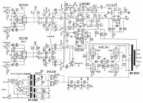
If a replacement can't be had, I am willing to hardwire this thing for 130V. (I'm in the US). How would I determine the load and neutral wires to use on the PT primary? I've attached the schematic I'm using. Any help is appreciated!
I'm working on an old Echolette M40 PA amp from the 60s. Four channel power mixer and from Germany.
I've run into a problem, however. One of the contact pins on the voltage selector switch broke while I was changing out the fragile (and entirely too small gauge wiring) from this thing to the PT primary.
The voltage selector switch is a six-positon. (110-130-150-210-230-240v). The only identifying mark is the word "Philberth" on the face. Google doesn't yield anything. Anyone familiar with these? Where to get a replacement?
If a replacement can't be had, I am willing to hardwire this thing for 130V. (I'm in the US). How would I determine the load and neutral wires to use on the PT primary? I've attached the schematic I'm using. Any help is appreciated!
Attachments
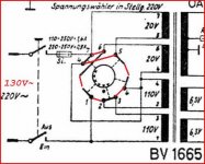
It was not clear to me how the switch exactly works, but another schematic shed some light on this.
The text in your schematic indicates that the setting in the schematics is for 220 V operation. This puts both 110 V windings in series and leaves the 20 V windings floating. I wasn't sure how to wire it for 130 V (windings must be in phase, of course), so I googled your amp and found another with a better schematic and all possible selector switch settings drawn:

http://www.jogis-roehrenbude.de/Roehren-Geschichtliches/EL503/M120.jpg
Now, this is a different transformer, but it seems to be wound exactly the same way using exactly the same numbering system for both transformer and selector switch. The drawings are mirrored with respect to those of your amp.
My educated guess is that the 130 V drawing is suitable for your amp as well. But be safe and make sure to test the setting (or rather equivalent hard wiring) with a bulb in series to prevent a catastrophe in case things turn out to be wrong...
What I'd do: label the wires with the corresponding numbers on the selector switch and desolder them. Then interconnect the wires as follows:
1 to 2;
3 to 4;
5 to 4;
6 to 7.
"Schalterstellung" = switch setting.
The text in your schematic indicates that the setting in the schematics is for 220 V operation. This puts both 110 V windings in series and leaves the 20 V windings floating. I wasn't sure how to wire it for 130 V (windings must be in phase, of course), so I googled your amp and found another with a better schematic and all possible selector switch settings drawn:
http://www.jogis-roehrenbude.de/Roehren-Geschichtliches/EL503/M120.jpg
Now, this is a different transformer, but it seems to be wound exactly the same way using exactly the same numbering system for both transformer and selector switch. The drawings are mirrored with respect to those of your amp.
My educated guess is that the 130 V drawing is suitable for your amp as well. But be safe and make sure to test the setting (or rather equivalent hard wiring) with a bulb in series to prevent a catastrophe in case things turn out to be wrong...
What I'd do: label the wires with the corresponding numbers on the selector switch and desolder them. Then interconnect the wires as follows:
1 to 2;
3 to 4;
5 to 4;
6 to 7.
"Schalterstellung" = switch setting.
Last edited:
Simple turn the selector position one step clockwise.I am willing to hardwire this thing for 130V. (I'm in the US). How would I determine the load and neutral wires to use on the PT primary? I've attached the schematic I'm using. Any help is appreciated!
Mona
Attachments
Thanks for the explanation and diagrams. That cleared up the switch issue!
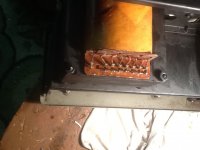
Both the PT and OT were disconnected when I received the unit. I've attached a picture of the PT primary side. Is the pinout of the schematic likely to be the same as the transformer? (1-3-2-4-4-6-5-7 or 7-5-6-4-4-2-3-1) Which end would be 1 and which 7?
Is there a way to test the primary windings for impedance and determine which is which? Thanks again!
Attachments
I'm surprised the original transformer doesn't have numbered terminals...
Yes, you could determine the windings by measuring the resistance. A 110 V winding will have much more wire than a 20 V winding. Assuming all (primary) windings are wound using the same wire gauge, there should be quite some difference in resistance between 20 V and 110 V windings, the 110 V windings' resistance being roughly 5 times as high as the 20 V windings.
From the schematic you can see that the outer 110 V and 20 V windings are isolated from eachother and from the inner windings. The inner windings are connected together at a "centre" tap (terminal 4). This should allow you to measure the resistances and draw out were which windings are. This will also allow you to determine where terminals 1 and 7 are.
Edit: it's possible that the terminals are numbered chronologically 1 through 7 and that two wires are connected together on terminal 4. In your photo, I can see one wire that's quite a bit thicker than the rest, that might be terminal 4. That would put no. 4 on the fourth position when counting from right to left. That would also mean that the eighth pin, far left, might be the (earthed) shield between primary and secondary windings (also pin 8 in the schematics in my previous post, your's doesn't show it, though). No doubt that's why it is positioned apart from the other 7.
I wouldn't be suprised if your transformer is numbered like this (but measure it to be sure):
8 - x - 7 - 6 - 5 - 4 - 3 - 2 - 1
Last edited:
Thanks for taking the time to help me with this matter. I am very appreciative. Just to clarify, though, pins 1 and 7 will be hot, neutral lines?
I will try to get back to this thing this afternoon after I tend the garden. I will leave an update after I do.
I will try to get back to this thing this afternoon after I tend the garden. I will leave an update after I do.
Last edited:
OK, I might read it later today or maybe tomorrow (it's 17:01 here now, ehm, 5:01 pm).
Please note that I edited my post after your reply.
Please note that I edited my post after your reply.

Thanks Mooly. I should have looked before I posted.
As an update, I went ahead and measured resistance between the pins. Here are the results. You appear to be correct in the order of the pins.
1-3 : 6 ohm
2-4 : 6 ohm
4-6 : 1 ohm
5-7 : 1 ohm
Is it normal for the resistance to be this low? The ratio between the turns appears to be about on point, at 1:5-6.
Now I need to figure out the PT secondary and the OT! Still a lot of work to be done on this thing!
Yes, DC resistance will give a rather low reading, but at 50/60 Hz, AC resistance will be higher.
Also measure between 1 - 7 and 2 - 6 to make sure the windings are actually the same as those in the schematics. 1 - 7 should read open, 2 - 6 should read approx. 7 ohms.
Keeping an eye on the schematics, you should be able to do the same thing for the secondary windings and the OT.
Also measure between 1 - 7 and 2 - 6 to make sure the windings are actually the same as those in the schematics. 1 - 7 should read open, 2 - 6 should read approx. 7 ohms.
Keeping an eye on the schematics, you should be able to do the same thing for the secondary windings and the OT.
I measured the remaining taps as you instructed. 1-7 measure open, while 2-6 measure about 7 ohms.
I'm going to continue working on the PA and hopefully I can deduce the windings on the secondary and the OT. Thanks for all your help.
I'm going to continue working on the PA and hopefully I can deduce the windings on the secondary and the OT. Thanks for all your help.
- Status
- Not open for further replies.
- Home
- Live Sound
- PA Systems
- Voltage Selector Switch