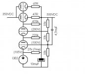
It has been a while since I build Frank’s pre amp with regulated PS, a nice and good sounding project. I build it with the regulator as from Frank’s schematics, but I had some trouble sourcing the tubes used – I admit, they aren’t that hard to find, but can cost quiet a bit when you need more regulators. So I started thinking about an alternative and stumbled upon the regulators based on the ECL85 – I found at least three, but all aimed at a 250VDC, while I needed (at least) 300VDC. Surely it’s possible to make a regulator for 300VDC with a ECL85, but I am also charmed of the idea of cascoding triodes for the error amp (just like in Frank’s regulator) to get more amplification, resulting in a (even) lower output impedance.
In my search for cheap tubes I found, beside the ECL85, lots of ECL84. The transconductance from this one seems to be at least as good as from the EL86, widely applied in regulators. Problem of the ECL84 is it’s relative small plate dissipation, in triode mode about 5W, I believe. Hum…what to do? Use two!! Parallel the pass devices (the pentodes of this tube) and put the triodes in a cascode. Even before consulting any theory on the matter, I realised that paralleling the output of the pentodes could give problems because of the very low output impedance. But I went further: I read the articles from Broskie, from steve bench, some books from Elektor, compared schematics of regulators, but beside a small mention from steve bench and frank’s regulator, I didn’t find anything more using a cascode error amp in a regulator. And my search for cascode circuits wasn’t that productive too. So I decided to go for the trial and error, and the support of diyaudio members.
I designed the regulator using two ECL84 and a OB2. I adjusted the resistor which sets the current for the OB…there is now 7mA running through the OB2 (plus any current coming from the triodes of the ECL84!!??). The OB2 regulates at 105V, that way I settled the voltage at the grid of the lowest triode at 100V. I read somewhere that the grid of the upper triode must be at approximately a fixed potential of 80VDC. I added the value of the OB2 to this, and to make things easier set the upper grid voltage on 200VDC, allowing the use of three resistors of the same value. The plate resistor for the lowest triode I copied from Frank (the use of this plate resistor allows some more current flow through the lowest triode, giving better results…so I read). For the plate resistor of the upper triode I took a 470k, half of what Frank uses (a lower value here gives less amplification, but some more current through the circuit).
The value of the capacitor from the regulated output to the grid of the lowest tube I defined according through this formula, which I took from www.tubecad.com. Don’t know if it is right (Frank’s regulator uses almost a decade less)
C >> (R1 + R2)/(2*pi*f*(R1*R2)
C>> (66.000 + 33.000) / (2*pi*2*(66.000*33.000)
C>> 3,61*10-6
C>> 3,61muF
(f is the lowest frequencies for which the regulator will be used, maybe 2Hz is to low).
Well, that was it. I greatly appreciate anyone’s input on this.
Attachments
stupid, stupid!!!
Of course that what I have done with the resistor setting is a stupid thing - it will not just settle itself on 300VDC at the output.
I have got the following formula to calculate Vout of a cascode circuit.
Vout = -Vin * mu 1 * Ra (Ri 1 + ((Ra + Ri 2)/(mu 2 + 1)))
In my schematic Ra is 470.000. Values of mu 1, mu 2 and Ri (internal resistance) are dependent on the conditions in which the valve is operating. If I take them from data sheet, they are as follow.
Typical characteristics triode section as AF amplifier
µ = 65 at Va = 200V, Vg = -1.7V, Ia = 3mA, S = 4mA/V and Ri = 16.200 ohms. Filling this in gives
Vout = 1296 * -Vin, what seems a bit too much.
So...ahh... I'm stuck. Maybe prototyping, using potentiometers... but how would this be done in the 'theoretical' way?
Attachments

Negative feedback loop. Don't consider the gain (BTW I think your equation is for AC signal 😉 ), consider the voltage divider chain.
Tim
Tim
so build option 2
Hi Tim
Now you talked about negative feedback I see that this circuit really uses it. And about that equation, indeed, is meant for AC
So, you think it should work using the pot to adjust the desired voltage?
And something else...I hope to join you in the MP amplifier idea (and implementation)! I've already been thinking about some issues about it (which tube to use, bias arrangements for correct balancing), but haven't gone further than that.
Erik
If you want to vary voltage on that circuit, change the middle and bottom 33k resistors to an, uh, 66kohm pot. Good luck with that; 47k for the top resistor and 100k for the pot will be easier to find. Keep the capacitor from output to pot wiper -- couples ripple to the error amplifier, improving rejection.
Tim
Tim
Hi Tim
Thanks for your help! I greatly appreciate it. It's not that I want to vary te output that much...just trying some fine adjustments here.
Erik
Thanks for your help! I greatly appreciate it. It's not that I want to vary te output that much...just trying some fine adjustments here.
Erik
Yep, either is possible. If you want to restrict range of the potentiometer, just subtract some from the ends and add it back in as fixed resistors, for example taking my previous values, you could use a 20k pot with two 40k resistors.
Tim
Tim
Hi
When I checked duncanamps for the exact pinout of the ECL84 i found this note: g3 of pentode connected to triode cathode. Checking some of the datasheets I found that g3 is connected to a (kind of) screen between triode and pentode. I've also just measured impedance between g3 and cathode, but there is now connection between them. So I will go further with this one.
A fast question, actually two questions. I want to use perforated board for the prototype. I'm leaving one track between the high voltage (~350VDC) and other voltages. Any idea about possible sparks?
And about the needed reference voltage. I will be using a OB2 now because they seem to be "better" than stacked zener diodes, which produce too much noise. I wonder if reduced noise, but still using SS, could be obtained from the combination of a voltage reference as the REF02, amplified to about 60VDC through a power opamp supplied from a single rail (like a opa541 that can take 70VDC). In the original circuit the OB2 (or zener) will have some current from the cascoded triodes flowing through it - can a (power) opamp handle this current?
Thanks, many thanks
Erik
I don't know where people are getting these ideas from. Zeners are way quieter BECAUSE you can put massive capacitance across them. Try that with a 0B2, hope you have a lot of spares! 😀
Tim
Tim
Hi Sch3mat1c
Thanks for the reply. I will try zeners with some big capacitance! I was just thinking of using the OB2 because I (think I) can get them for 0,50 euros/each.
Erik
Thanks for the reply. I will try zeners with some big capacitance! I was just thinking of using the OB2 because I (think I) can get them for 0,50 euros/each.
Erik
s2kov said:How about using two OD3 tubes in series to get 300V regulated supply?
Could be done - sure. I have made this one thinking it would be better, but I don't know. Maybe I stack 3 OB2 (about 324VDC) for a comparision with the 2x ECL84 and zeners / 1 OB2 that's almost finished on my breadboard (waiting for my new welding iron).
Erik
I suggest to first write the equation of the "open-loop" in frequency domain to see where your Pole and zero is located....
Then write the equation of the feedback circuit also in frequency domain....The summation of both equations should yield good stability and phase margin....
Especially for audio, make sure this loop response is stable and well damped to transient step response....
Chris
Then write the equation of the feedback circuit also in frequency domain....The summation of both equations should yield good stability and phase margin....
Especially for audio, make sure this loop response is stable and well damped to transient step response....
Chris
Many thanks
Hi Cerrem
I thank you very much for your reply. At a first moment I can't do anything with it, but it can help me trough some theory - meaning reading - do you have a suggestion where I can find the needed theory?
For now I see it's better to stay with a proven design.
Erik
Hi Cerrem
I thank you very much for your reply. At a first moment I can't do anything with it, but it can help me trough some theory - meaning reading - do you have a suggestion where I can find the needed theory?
For now I see it's better to stay with a proven design.
Erik
I will do the analysis and diplay the results....
Nothing is "proven" until you do the proving yourself....
The key info need is what is the load range this regulator will see ??
I see a few problems with this particular reg circuit...
As for reading....find a control theory book...It should go over margin of stability for Gain margin, Phase margin, loop analysis, Nyquist, BODE kind of stuff.....
Chris
Hi Chris
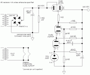
Thank you for doing the analysis. I plan to use this regulator for loads for both phono and line stages, one regulator per channel. The first, using 1 ECC83 will be drawing less than 5mA. For the line stage I have not decided exactly what topology and tube I will be using, but I think the load won't exceed the 20mA used through the 12BH7A in the attached schematic (with a B+ of 300V and R2, R4 = 15k; R3 and R5 = 500R), schematic from John Broskie, published at glass-ware. I also want to try a Aikido line stage, but this won't be drawing more than 20mA (with the tubes I am planning). So between 2 and 20mA...
But, eventually I want to go to a balanced system. Balanced prepre/linestage imply in a double current drag from the power supply, ie, between 4 and 40mA. Do you think this regulator could handle that?
My first thouhgt was that it could handle it, based on the 40mA maximum allowed current through the cathode of the ECL84. 2 tubes would give 80mA, plenty to supply linestage + current drag from the own regulator. Also plate dissipation wouldn't be a problem, because, when lets say, there is a voltage drop of 100V across the tube and a current drag of 50mA, total plate dissipation would be 5W, while maximum plate dissipation from each is 5W. Or is my thought to simple?
What kind of problems do you see with this regulator? As I said, I've a breadboarded version almost finished...is it safe to at least try it? 🙄
Well, if it doesn't work at least I have learned something from the whole thing, specially from your input.
Erik
Attachments
To be totally honest...I don't see the point of using the Cascode arangement when you get similair results with a small pentode...such as a EF86 or such... The advantage with the Cascode of a 12AX7 is the cost of a 12AX7 is dirt cheap next to a quality little pentode like a EF86, which happens to be one of my favorite small signal pentodes.... I like using 6V6 or EL84 valves for pass tubes, due to the small size and power handling and low cost, last I checked 🙂
Remember that when setting the idle current for the regulator tube...not only do you acount for the 68K current limit resistor but you also need to account for the cathode current from the the lower triode, which is also getting jacked up a bit from the 220K resistor.... Sum both of these currents... From what I remember the 0G3 and 5651 have different specs for idle current...
When calculating the gain of the Cascode....remember that the grid of the upper triode is not 100% bypassed and that .605 of the output ripple will appear at this node and cause negative feedback...which is good..
The Error amp has a pole roughly at 14Hz....rolloff of -20dB/Decade from the DC gain of that Cascode stage.....
I will take another look at it later...
Chris
Hi Chris
I thank you for the reply. I understand the question of why using a cascode for the error amp. My reason is that with an ECL84 you have a little plate dissipation...so use two for double power dissipation in the regulator...if you use two, use both triodes in a cascode, for higher amplification and lower output impedance. I knew it must be possible, Frank de Grove uses one cascoded ECC83 in his regulator, shown above.
I choose the ECL84 because they can be had dirt, dirt cheap - but you can say the same from a ECC83 and some other tubes (like an EL86) used as pass element - and when you have a bit of a nice design, plate dissipations from both will be so low that should last a lifetime. But, anyway...I wanted to give the ECL84 a try...could also be ECL85 or a PCL82 - but I'm saving this one for the MP project of Tim 🙂
And about using penthodes. I do have some EF86 to...8 pieces. I don't think I am going to use them in any design, but for the regulator I want to use tubes I can buy a bulk for some euros. Maybe I can use a common TV penthode, but I can't think of any with high gain right now.
I will compare zeners and tube regulators in this design. If I go for the tube regulator I will be using the OB2. They can handle up to 30mA. The idle current I selected subtracting the voltage reference value from the output voltge and dividing it by 7mA (which is maybe to low). I choose a 27k resistor... you mention a 68k resistor - I think you took that from Frank's schematic (but Frank uses a 85A2, which can handle much less current than an OB2). Well with 7mA there is enough current that can come from the triode's - if we have to worry about something, we have to look at how much current is going through the triodes, which I believe isn't much (less than 1mA). So maybe the 27k resistor can even be a bit lower in value.
And now I am going to bed
Erik
Just a question
I got two PCL200 valves from a guy and looking at the datasheet they seem nice for a voltage regulator (high transconductance). So I put them in a circuit using basically the same schematic as I used for the regulator using the ECL84 (two tubes: paralleled pentodes, trioded connected and used as pass elements, triodes are cascaded for higher gain). But the performance was bad. For test purposes I was aiming at 280V and 80mA, so I used a dummy load of 3k5. Using a variac and a simple PS I slowly turned the input voltage up and the output from the regulator started following, but way to slow. Eventually the raw B+ was around 420V and the output from the regulator was at about 220V. This implied in a voltage drop of about 200V across the PCL200’s…(and about 7W plate dissipation each, close to their maximum ratings)
I thought, well, I am a newbie, so I will go a bit slower. I assembled a regulator using just one PCL200 (and the OB2) according to this schematic Now I aimed for about 250V and 30mA, but again there was a voltage drop of about 200V across the tube. I tested an ECL85 in the same circuit and it could deliver a total of 50mA (what is above its maximum ratings) with a voltage drop of only 90VDC.
If I had the curves for a triode connected PCL200 I would know what is going on, but I don’t have it. So my question is, what is wrong with the PCL200 – why there is such a large voltage drop across it? Is it something I can read from the datasheet?
Many thanks for your attention (and in the mean time I will use the ECL84 regulator, which works quite nice).
Erik
- Status
- Not open for further replies.
- Home
- Amplifiers
- Tubes / Valves
- voltage regulator using ECL84 + OB2