Using solid state bias control for each tube so no cathode resistor just 2 X 100 ohm resistors to g2's.
Do the G1's and anodes settle to about the expected voltages?
Here is the ccs circuit, source follower isn't used in this application
You could check what happens without C1, although a too large C1 would probably lead to blinking independent of what happens with the valves in the signal path.
Yes as far as I can tell obviously if there is no voltage being applied to g2 then it's difficult to be certain
If you take out a single input tube & leave the output tubes in, it strikes & stays good, so the signal being received has an effect on the output, all biasing sitting at -27VYou could check what happens without C1, although a too large C1 would probably lead to blinking independent of what happens with the valves in the signal path.
It doesn't restrike, also there is 75V sitting on the output of the tube after it drops outThat means that there is a capacitor charged above the striking voltage causing the tube to strike. However there is a high resistance feeding the voltage to the capacitor. So the tube strikes an arc, the voltage drops until the arc extinguishes and then the voltage will begin to rise until the striking voltage is reached again. This is known as a relaxation oscillator. It happens because the striking voltage is higher than the regulation voltage and there is a resistance in the voltage source that limits the current below what is needed to maintain the regulation. If there is a tube rectifier that would be the first suspect.
As your tube does not restrike then there is not enough current driving it. So I would look at your current limiting bit. Seems there is a load that effectively kicks in after the strike. I would look at the tube it is driving.
Probably easy to move tubes from one socket to another.
Absolutely no (!) capacitors allowed across a voltage regulator tube! Omit that 47 nF and report again, please!
Best regards!
Best regards!
Not true. Shunt capacitor maximum = 0.1uF according to this datasheet: https://frank.pocnet.net/sheets/137/0/0B3.pdf and https://frank.pocnet.net/sheets/049/0/0A3.pdf
First cap 47nf then 47k resistor then 4.7uf, which works fine on other channel, it's just first cap needs to be low, the same as if you were using capacitors for a tube rectified PSU!
Either the current source delivers too little current or G2 of the pentode draws too much. I can't see any other reason why the voltage would get stuck far below the 0A2's striking voltage after it has turned off again.
If the removal of the input valve isn't supposed to affect the DC bias point of the pentode, could it be that there is something oscillating?
If the removal of the input valve isn't supposed to affect the DC bias point of the pentode, could it be that there is something oscillating?
Not true. Shunt capacitor maximum = 0.1uF according to this datasheet: https://frank.pocnet.net/sheets/137/0/0B3.pdf and https://frank.pocnet.net/sheets/049/0/0A3.pdf
Sorry didn't see Kay's reply, You are correct 0.1uf maximum, taking 47nf out might cause a problem if 4.7uf is there. There are separate power transformers for each channel. 1 channel works fine with this scheme, the other does not, you can swap the set of tubes out from the good channel & put them into the bad channel, fault is just the same
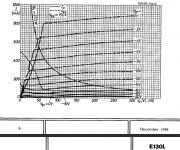
If I take both power tubes out & plug one power tube back in the voltage sits at 140v then drops back to 80v when it starts to get hot, (without anode caps attached) VR tube is still struck but very dim, if I plug the other one in it is even dimmer but still on at 40v, the tubes are E130L's
I'd give it more current to work with and or a higher voltage source. Seems like it's starving.
In my usage of VR75 for negative grid bias voltage regulation, I feed it with 110VDC through 1k5.
In my usage of VR75 for negative grid bias voltage regulation, I feed it with 110VDC through 1k5.
very strange that the other channel works if you put the same complement of tubes in it including the 0A2, but I will halve the resistance & see what it does
very strange that the other channel works if you put the same complement of tubes in it including the 0A2, but I will halve the resistance & see what it does
isn't that a clear indication that it is not the tubes and not the regulators which cause the problem; unless you haven't inadvertently connected something to the G2 socket pin, which doesn't belong there (double check), it all comes down to the ccs; it seemingly does *not* provide the 18mA although you think it does. This can be measured: I would take all the tubes out and measure the current with an amp-meter connected across the socket pins of the 0A2. I bet it reads something much lower than 18mA.
if that were the case, it could be a faulty or miswired component, or a resistor which sets the current is wrong (similar color stripes but 10x off, red instead of brown as 3rd ...)
Last edited:
checked everything there but I will do as You suggested, but that 0A2 works fine on the other channel, they are basically 2 mono amps in one box, even 2 separate power transformers, I have spare CCS which I swapped
I know it must be taken into account that the VR tube sucks up current too, I am now wondering whether the so called faulty channel is the good one & perhaps something in the other channel isn't conducting, therefore not taking current as it should.
If I take both power tubes out & plug one power tube back in the voltage sits at 140v then drops back to 80v when it starts to get hot, (without anode caps attached) VR tube is still struck but very dim, if I plug the other one in it is even dimmer but still on at 40v, the tubes are E130L's
With the top caps not connected, the E130L's will draw more screen grid current than they normally do.
Attachments
ok I took out the 47k resistor & put in a 2.7k, this made no difference, also changed 4.7uf cap for a 1uf, these changes did nothing.I'd give it more current to work with and or a higher voltage source. Seems like it's starving.
In my usage of VR75 for negative grid bias voltage regulation, I feed it with 110VDC through 1k5.
The regulator on the other channel, CCS has a 10 ohm resistor in series so if you measure across that it reads 1.8mV & it can be reduced to minimum on pot to 5mA & still strikes & stays at 145V, but this makes no difference to operation wherever it's adjusted to.
Right yes if you put caps on it strikes & goes out immediately whether using a 2.7k resistor or 50k, BUT if you take the first tube out or the voltage divider it strikes back up & stays on, scratching my bald head now!With the top caps not connected, the E130L's will draw more screen grid current than they normally do.
- Home
- Amplifiers
- Tubes / Valves
- Voltage Regulator Tubes