I'm "refreshing" an Adcom GDA-600 DAC and would like some tips on the PSU section. The unit is now 27 years old and I'll be replacing the caps in the power supply.
I'll be using Panasonic FC for the main filter caps.
The decoupling capacitors for the voltage regulators used here are Nichicon VX (standard) 10uF 35V and 0.1uF MLCC (not sure which type) for the LM317 and LM337 adjustment pins.
Most of the components in this unit look to be very solid choices but in this case it does seem to be economic as these caps are used throughout for various duties.
I've read through many LM7805 and LM317 datasheets but since some are 40 years old, perhaps with changes in capacitor technology and availability, better choices can be made.
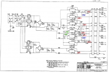
The schematic is attached with capacitors marked.
Red -- output decoupling caps
Green -- input decoupling caps for the regulators that are used by the PCM63-P DAC chip
Blue -- 0.1uF MLCC for the adjustment pins. (datasheets recommend 10uF-20uF here)
I would appreciate recommendations for each of these positions. As of now, I only chose 10uF solid tantalum for the output caps based on their usage in previous projects with the LM7805.
P.S. I'm replacing the LM317/LM337 with LT317AT/LT337AT which have slightly better specs.
I'll be using Panasonic FC for the main filter caps.
The decoupling capacitors for the voltage regulators used here are Nichicon VX (standard) 10uF 35V and 0.1uF MLCC (not sure which type) for the LM317 and LM337 adjustment pins.
Most of the components in this unit look to be very solid choices but in this case it does seem to be economic as these caps are used throughout for various duties.
I've read through many LM7805 and LM317 datasheets but since some are 40 years old, perhaps with changes in capacitor technology and availability, better choices can be made.
The schematic is attached with capacitors marked.
Red -- output decoupling caps
Green -- input decoupling caps for the regulators that are used by the PCM63-P DAC chip
Blue -- 0.1uF MLCC for the adjustment pins. (datasheets recommend 10uF-20uF here)
I would appreciate recommendations for each of these positions. As of now, I only chose 10uF solid tantalum for the output caps based on their usage in previous projects with the LM7805.
P.S. I'm replacing the LM317/LM337 with LT317AT/LT337AT which have slightly better specs.
Attachments
I don't think that these conventional positive regulators have any particular stability issues.
It is the low drop designs that are fussy about ESR
It is the low drop designs that are fussy about ESR
Output capacitance is not too critical on those. 10uF should be fine.
The adjust pin is a current source. The voltage created on the output is the reference voltage. Any ripple on this will result in ripple on the output. This should be very stable, hence a big capacitor is used. A diode (LED or zener) solution would give more stable results.
Depending on budget a nice film can be used here. Electrolytics are also fine and a much cheaper option.
Another important thing is the ESR. Too much ESR will lower the effectiveness of the capacitor. Too little and you will create a resonance with the output impedance. Choose a capacitor accordingly! You can also add resistance manually.
You can also try to linearise the output impedance of the regulator (output is often a emitter output which has an impedance as show in the slope of diode IV-curve) by adding a small current load. I like to use led's for this as they also give a visual indication on whether the PSU is working.
Thanks for your replies.
In the meanwhile, I did a bit of searching and found alot of inconclusive information on this topic. I am surprised that 40-50 years after these were released, there isn't a straightforward recommendation.
Resources such as:
* Regulated Supplies
* Datasheet -- https://intranet.ctism.ufsm.br/gsec/Applications/lm317.pdf
* https://electrooptical.net/static/oldsite/www/sed/ErrolDietzRegulatorNoisePeaks.pdf
* Using 3-pin regulators off-piste: part 3
* Simple Voltage Regulators Part 2: Output Impedance
Trying to aggregate all of this information, I am going to use:
1) Output -- 10uF Tantalum (previously 10uF "standard" electrolytic)
2) CAdj -- 10uF Nichicon UPW (previously 0.1uF MLCC)
3) Input -- 10uF Nichicon UPW (previously 10uF "standard" electrolytic)
I think the biggest difference here is increasing the capacitance on CAdj which most recommendations were in the 10uF-20uF range
is there a diode between Adj and Vout?. Put a large capacitor Cadj and shorting the output is likely to blow the regulator without one. A 1N4001 is the usual part.
I dislike tantalums on regulators, so many shorts over the years.
I dislike tantalums on regulators, so many shorts over the years.
Really? I thought these solid tantalums were known as ticking time bombs...?IAs of now, I only chose 10uF solid tantalum for the output caps based on their usage in previous projects with the LM7805.
I don't remember the exact source but I've read that some of their reputation is unjustified.
I use this KEMET part from the AMB sigma25 BOM:
80-T350E106K025AT
I can only rely on what I read as I dont have the knowledge or experience myself.
Here are some of the sources:
* LT317 datasheet: "Because of their low impedance at high frequencies, the best type of capacitor to use is solid tantalum"
* Reduce noise in voltage regulators: "For instance, a good 1uF PP capacitor ....produces a noise peak three times greater than that of the same value of tantalum capacitor with an ESR of 1..2 ohm"
* Op Amp Applications Handbook (Walt Jung) pg. 657 (showing an LM317 circuit): "In this circuit, capacitors C1 and C2 [input and output decoupling] should be tantalum types"
is there a diode between Adj and Vout?. Put a large capacitor Cadj and shorting the output is likely to blow the regulator without one. A 1N4001 is the usual part.
I dislike tantalums on regulators, so many shorts over the years.
Yes, as observed in the schematic there is a 1N4001 over there.
By the way, the datasheet mentions this to be an issue with the output decoupling capacitor is 100uF or over, not specifically an issue with CAdj.
I found out the hard way that some brands of LM317 need a very lossy capacitor at the output for stability.
I had decoupled the output of a 1.8 V regulator with an LM317 with two 10 uF X5R SMD capacitors (with a working voltage far above 1.8 V because of the voltage dependence of X5R). Sometimes everything worked as intended, sometimes I heard an annoying beep coming from the PCB. After reading something about LM317 output capacitors on this forum, I found out it was an oscillating LM317 with the X5R capacitors working as piezoelectric loudspeakers.
In the end I connected a 47 uF run-of-the-mill aluminium electrolytic capacitor in parallel with the 2 times 10 uF X5R and never heard the beep again.
Last edited:

- Home
- Design & Build
- Parts
- Voltage regulator (LM317, LM7805) decoupling capacitors