Help need with voltage regulator
Hey guys,
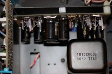
This was bound to happen from earlier indications but I think one of the voltage regulators on my power supply needs to be replaced. After some mods to my preamp the voltage readings were off again and this time I noted that one of the negative voltage regulators was extremely hot and the others were cool. Does this mean it should be replaced or is it a resistor on the board or diode that needs to be replaced? Furthermore, if it is the voltage regulator is that a simple switching of parts as well, or do I need any fancy instrument? Any suggestions on good upgrade replacement? If practical i will probably upgrade all 4 at once. The regulator in question is IC4 on the Board, uA79M24AJC


http://www.diyaudio.com/forums/attachment.php?attachmentid=274208&stc=1&d=1332915814

Hey guys,
This was bound to happen from earlier indications but I think one of the voltage regulators on my power supply needs to be replaced. After some mods to my preamp the voltage readings were off again and this time I noted that one of the negative voltage regulators was extremely hot and the others were cool. Does this mean it should be replaced or is it a resistor on the board or diode that needs to be replaced? Furthermore, if it is the voltage regulator is that a simple switching of parts as well, or do I need any fancy instrument? Any suggestions on good upgrade replacement? If practical i will probably upgrade all 4 at once. The regulator in question is IC4 on the Board, uA79M24AJC
http://www.diyaudio.com/forums/attachment.php?attachmentid=274208&stc=1&d=1332915814
Attachments
It may or may not be faulty. It's just as likely to be a fault drawing excess current. If so then after fixing the fault then replace the regs that fried.
You can either isolate the rails to check the regs or insert an ammeter into the feed from the reg and check the current draw. For a reg not on a heatsink you are looking at 100ma or so max give or take.
You can either isolate the rails to check the regs or insert an ammeter into the feed from the reg and check the current draw. For a reg not on a heatsink you are looking at 100ma or so max give or take.
It may or may not be faulty. It's just as likely to be a fault drawing excess current. If so then after fixing the fault then replace the regs that fried.
You can either isolate the rails to check the regs or insert an ammeter into the feed from the reg and check the current draw. For a reg not on a heatsink you are looking at 100ma or so max give or take.
Thanks again Mooly for your willingness to respond.
This is something new for me. Diagnosing sounds a little foreign to me still. This is going to really force me to understand how circuits work rather than just switching parts. 😀
So in order to check the draw I need to insert my DMM into the chain following the regulator. I assume this is with the preamp turned on so I don't need to worry about damaging anything having it turned on? W
here exactly do I place my probes? The back of the board is inaccessible when turned on because of the way it is placed into the chassis. Although, the regulators look fairly accessible from the top. Can I check it from the top of the board on the regulator pins?
So if there is excess current being drawn it could be a faulty bridge rectifier or transistor. If something is faulty is it likely to be on the same board or could it be on another board, like the output board? How do I find the fault? In the simplest terms please, do I need to trace the signal or pull each transistor out one at a time to test.
Attachments
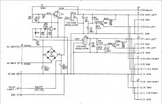
You have to break the feed from the regulator output to the rest of the circuitry it supplies. You mention IC4 in post #21 which I take it to be IC2 in the diagram ?
Best way is to unsolder the output pin of the reg (pin 2). Leave it "free" in the print. Now solder two wires, one to pin 2 and the other to the print pin 2 goes to. Extend the wires to your meter and set it to a DC current range of at least 1 amp. Switch on and check current. If there is a problem in the preamp it will show excess current . If the reg is faulty the reg will be hot but the current low.
If the excess current is due to the amp drawing it then you need to check all the work you have done and methodically isolate stages that run off that -24 volt line.
If something is drawing high current then it's possible that whatever that is, is also running hot.
Nearly forgot... before you do any of that what is the voltage on the -24 volt rail actually reading 🙂
You have to break the feed from the regulator output to the rest of the circuitry it supplies. You mention IC4 in post #21 which I take it to be IC2 in the diagram ?
Best way is to unsolder the output pin of the reg (pin 2). Leave it "free" in the print. Now solder two wires, one to pin 2 and the other to the print pin 2 goes to. Extend the wires to your meter and set it to a DC current range of at least 1 amp. Switch on and check current. If there is a problem in the preamp it will show excess current . If the reg is faulty the reg will be hot but the current low.
If the excess current is due to the amp drawing it then you need to check all the work you have done and methodically isolate stages that run off that -24 volt line.
If something is drawing high current then it's possible that whatever that is, is also running hot.
Nearly forgot... before you do any of that what is the voltage on the -24 volt rail actually reading 🙂
Both the negative 15 & 24 volt rail is reading full positive 15 & 24.
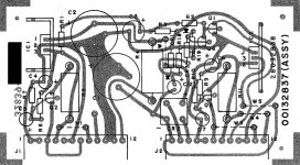
It looks like IC2 but is IC$ because the circuit repeats itself for left and right channels but it was only drawn once for some reason. If you look at the board you will actually see the 4 regulators. Also you can see IC4 printed on the circuit board.
Thanks for detailed instructions. Hopefully I will get to it tonight but now I have to get the kids to swim class. Have to work my hobbies around their personal schedules.😉
It sounds like there could be a problem in the main amp given the readings.
Recheck all the mods you did before this problem.
Recheck all the mods you did before this problem.
It sounds like there could be a problem in the main amp given the readings.
Recheck all the mods you did before this problem.
Hi Mooly,
I found a blown cap on the Output Board. I am not sure how this happened. Could have been a bad cap from a back supply of Blackgates. Never the less I want to go ahead and upgrade the regulators, which have suffered their fair share of me shorting out the circuit with the DMM probes. I never did get around to testing the regulator like you said but my plan is to replace the regulators and Bridge Rectifier, then reinsert the main power board with all the other boards removed and measure again. Then I will start reinserting the Output Board, Phono Board, etc making sure their are no fluctuations indicating a fault on the subsequent Boards.
One question. A while back I doubled the power supply caps on the main power Board from 1000uf to 2200uf and a few other caps along the way. Even the 10uf Blackgates compared to 10uf Elnas look intimidating like they may have a larger power draw. Can I, should I, or how do I select a better Bridge Rectifier. I do not know if I can increase the rectifier here but from what I gather more Amp & Volts is better. Is that correct and if so how big can I go? Are these 5.1V Zeners o.k. too?
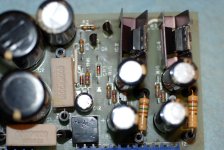
Power Board with Double Capacitance
Power Board with Double Capacitance
Attachments
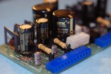
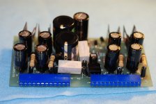
One question. A while back I doubled the power supply caps on the main power Board from 1000uf to 2200uf and a few other caps along the way. Even the 10uf Blackgates compared to 10uf Elnas look intimidating like they may have a larger power draw. Can I, should I, or how do I select a better Bridge Rectifier. I do not know if I can increase the rectifier here but from what I gather more Amp & Volts is better. Is that correct and if so how big can I go? Are these 5.1V Zeners o.k. too?
Physically larger caps usually have the capacity to allow more ripple current to flow. That doesn't mean it does though as that depends on the circuit.
A cheapo 1000uf and the worlds finest 1000uf will be passing the same AC ripple current in this circuit. The cheapo may fail earlier than the best if that current happened to be near its rated limits.
So there is no problem there... the cap doesn't "draw" more power because it is large or better quality.
Increasing the caps from a 1000uf to 2200uf will not be an issue but it's worth remembering that just increasing the value of caps on the basis of "more uf must be better" doesn't always follow. Doing so can increase something called "copper losses" in the transformer meaning that it can saturate and run hotter than it should. This is because the overall power drawn by the circuit is constant, but the larger caps need a higher current over less time to put that energy back. That's because the voltage across the larger value cap "sags" less between each half cycle (the ripple voltage is lower), but the same energy has to be put back making the current pulses larger.
Personally I don't think altering the bridge will make much difference. What comes out of the regs is what matters. Diodes should have a high enough P.I.V. (peak inverse volts) rating and sufficient current and surge current (for charging the caps). If you were changing them then look for soft recovery types... can't bring any specific devices to mind without looking at data sheets.
Unless the zeners have been zapped they will be fine. Just make sure the volt drop across them is as per the marked value within say 10%
Mooly, thanks again. Maybe I am getting a little smarter but your explanations are very easy to follow. Increasing capacitance for the sake of it is one of the beginner faux pas that I am unlearning. If at least I have learned from listening that there is only so much one can squeeze out of a circuit with premium parts before the point of diminishing returns starts to kick in. Never-the-less these parts are 40 years old and the voltage was drifting even before catastrophe so I will replace like for like but now I know not to just go and increase the rectifier for the sake of having more Amps and volts. Thanks for being my resident expert in this thread - you should be a moderator.😉 Can I mail you a pint of beer?🙂
Well I went a head and replaced the voltage regulators and bridge rectifier and removed every board from the preamp except the power supply. After which the negative voltage rails improved but are still off. Both neg 15V rails read -2.2 & both neg 24V rails read -4.9. The problem therefore is definitely on the power supply board. I can only assume that its one or both of the diodes? CR1 or CR3.
The manual says CR1 is 1N914 - not sure how to read that. CR3 is Zener, 5.1V, 5%, .4W
Any further advice. Might as well replace everything on the board at this point.
The manual says CR1 is 1N914 - not sure how to read that. CR3 is Zener, 5.1V, 5%, .4W
Any further advice. Might as well replace everything on the board at this point.
We go back to basics 🙂
So looking at the diagram in post #21 we measure the DC voltage across C1 and C2 with respect to ground. There should be around -/+35 volts DC across each.
CR1 and CR3 are used to help provide a quick "turn off" for the relay drive. They have no influence on the main rails.
Measure those voltages on the caps first and see what is going on.
We go back to basics 🙂
So looking at the diagram in post #21 we measure the DC voltage across C1 and C2 with respect to ground. There should be around -/+35 volts DC across each.
CR1 and CR3 are used to help provide a quick "turn off" for the relay drive. They have no influence on the main rails.
Measure those voltages on the caps first and see what is going on.
Thanks Mooly,
C1 is 42V and C2 is 40V. Therefore ....
Therefore.....
you trace on the circuit where they go, and that is pin 3 of IC2 for the negative rail. So you should have -42 volts on there (C1 voltage). So check.
If so then measure on the output pin of the regulator directly, that's pin 2 the middle leg. That should be -15 volts. Also confirm the ground pin of the reg is at zero volts.
If there is no output and yet the -42 volts is present on the input then something fundamental is wrong around the regulator. Is the regulator cold ?
If we still have no -15 volts then to "prove" the regulator we have to isolate the output pin completely and see what voltage is there. If you do that I have a dim recollection that the negative regulators of the 79 series might need a small load to work correctly such as 1k resistor.
Just because the regs are new doesn't mean they are above suspicion. We have to prove it step by step.
Therefore.....
you trace on the circuit where they go, and that is pin 3 of IC2 for the negative rail. So you should have -42 volts on there (C1 voltage). So check.
If so then measure on the output pin of the regulator directly, that's pin 2 the middle leg. That should be -15 volts. Also confirm the ground pin of the reg is at zero volts.
If there is no output and yet the -42 volts is present on the input then something fundamental is wrong around the regulator. Is the regulator cold ?
If we still have no -15 volts then to "prove" the regulator we have to isolate the output pin completely and see what voltage is there. If you do that I have a dim recollection that the negative regulators of the 79 series might need a small load to work correctly such as 1k resistor.
Just because the regs are new doesn't mean they are above suspicion. We have to prove it step by step.
I measured IC2 and the input was 40V and the output was 5V and the ground was zero. I already replaced R 1,2,18. The only resistor I missed on my order was R3. What do I measure next?
Last edited:
I went back over the spec sheets for the voltage regulators and noticed that I ordered them wrong. 😀 I did not realize that the last 2 numbers of the regulator type specify the voltage output. The voltage regulators I put in are actually working like they are suppose to. Regardless another lesson well learned. Back to ordering parts again. Thanks Mooly for your patience with me greenness.
No problem 🙂
Make sure you don't mix the 78 and 79 types too (pos and neg)
Funny enough I will be honest and tell you that I did originally. I noticed that first and the reason I mixed them was because of the way the circuit diagram was drawn only showing half of the board leaving me to deduce the positions on the other half of the board. I have changed all the resistors to 1% metal film with the exception of 3 that I missed so after this order of parts everything should be better than new. Hate paying $20 shipping for $5 worth of parts though. I'll let you know when everything is up and running.
- Status
- Not open for further replies.
- Home
- Source & Line
- Analog Line Level
- Voltage Readings Following Soldering Error