Thank you mooly for extenstive teaching in this area. I stared at the diodes for a while and then came back to it. Voltages are way up now but for some reason, my regulators became inactive after changing transformer secondaries and closing all four diodes. I did further homework and learned about protection diodes on regulators. This project has become loaded with lessons.
Wow this is a strange circuit I have everything working. I was having some difficulty getting my second circuit up to 48Volts. Now that it is up to 48 Volts, the LM317 is only allow a maximum of 35Volts out. I had the same issue with LM337. It only works properly when incorrectly wired. It is a Fairchild. I had to swap inputwith output to get it to provide max rail voltage.
Hi ! i found this old thread on voltage multipliers and i thought reasonable to attach here my kind question
i do not know if what i have attached is that of a voltage multiplier schematic
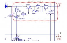
I really need some help to understand what those two 2sd667 do the DC voltage ... do they increase it ? how much ? how the multipligation factor can be calculated ?
If someone can direct me to some explanation of this circuit i would be very grateful.
I would like to increase the Vgain even further to mod a unit.
But i do not know if i have to change resistors and bjts with more powerful/higher volatge ones.
Current need about 1A absolute max ...
Thanks a lot to anyone
Have a nice day
gino")
i do not know if what i have attached is that of a voltage multiplier schematic
I really need some help to understand what those two 2sd667 do the DC voltage ... do they increase it ? how much ? how the multipligation factor can be calculated ?
If someone can direct me to some explanation of this circuit i would be very grateful.
I would like to increase the Vgain even further to mod a unit.
But i do not know if i have to change resistors and bjts with more powerful/higher volatge ones.
Current need about 1A absolute max ...
Thanks a lot to anyone
Have a nice day
gino
Attachments
Last edited:
TR1 is a main active element of an active low-freq filter (a cap multiplier). TR2 is just an overcurrent protection.
To make it work up to 1 A you have to set up that protection to a bit higher than 1 A.
Ube of any bipolar transistor is about 0.5-0.6V when it starts to open, so R4 = 0.5V/1A = 0.5 R.
So, you may begin with R4 = 0.47 Ohm 1W.
You have to decrease the value of R5, of cause, too.
To make it work up to 1 A you have to set up that protection to a bit higher than 1 A.
Ube of any bipolar transistor is about 0.5-0.6V when it starts to open, so R4 = 0.5V/1A = 0.5 R.
So, you may begin with R4 = 0.47 Ohm 1W.
You have to decrease the value of R5, of cause, too.
Last edited:
TR1 is a main active element of an active low-freq filter (a cap multiplier). TR2 is just an overcurrent protection.
Hi ! thank you so much for your kind reply and very helpful advice.
Please let me elaborate a little. I have found this schematic and i wanted to understand what is the function of the circuit included within the dotted line
So it filters the ripple without increasing the incoming voltage. Great !
I do not think that it also regulates the voltage because i do not see any zener
can a voltage regulation function be added maybe placing a zener diode at TR1 base ?
Thanks a lot, I have understood No problem. I said 1A but it could be much less actually It is for preamps. When i will have the current i will calculate the R as you instruct.To make it work up to 1 A you have to set up that protection to a bit higher than 1 A.
Ube of any bipolar transistor is about 0.5-0.6V when it starts to open, so R4 = 0.5V/1A = 0.5 R.
So, you may begin with R4 = 0.47 Ohm 1W.
You have to decrease the value of R5, of cause, too
There is a mirroring negative part with 2sb647 complementary parts to get the negative rail.
Is it possible to add V regulation also ?
Sorry .. i understand only now that i am OT ? what i have to search ... cap multiplier ? sorry again
Last edited:
Hi again, in understand now that my question was completely OT and i feel sorry for that.Yes, you may add a Zener in parallel to C3 or after R3. The filtering effect will lower but it will regulate a voltage with a Zener stability.
Anyway i end here saying thank you very much to you. I am very interested in AC ripple filtering techniques applied in particular to smps.
I already knew of passive filters like RC or LC or more complex combinations of L, R and C. I knew nothing about active filters i will be trying to learn something, for instance the advantages of active versus passive filtering. I understand that the circuit that i have attached acts also as a cap multiplier ? so smaller caps can be used with an enhanced effect ?
Thanks a lot again. Have a nice day, gino
- Status
- This old topic is closed. If you want to reopen this topic, contact a moderator using the "Report Post" button.
- Home
- Amplifiers
- Power Supplies
- Voltage multiplier