Hi
I am building an "op-amp" from first principles. Currently I am trying to shift the DC/AC audio signal from Vs/2 to 0.
I am trying to create (and understand) a voltage level shifter. I have seen a design (original 741) but I cannot understand it as it is incorporated in the diff amp stage. I know it'd be quite simple and it'd take probably one transistor and one resistor to make.
Can anynone please show me a circuit that does it so I can understand it?
Thanks
Akis
Currently I am messing with "cascode" transistors, ie two or more in series, but I am not there yet 🙂
There are basically two ways to translate an AC/DC signal to a different voltage base level:
1. convert it into a signal current, then back into a voltage e.g. cascode
2. interpose a floating voltage source e.g. Vbe multiplier
If the signal is AC only, then two more ways are available:
3. use a capacitor, with either a resistor or switch on the output side
4. use a transformer, with the output side biassed to the desired voltage
You could add optoisolation as a further method but this is only used when significant isolation (of voltage or ground currents) is needed.
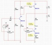
Here is a circuit I have been experimenting with.
( Q3 and associated components is not part of the voltage shifter and only used to drive it for verification purposes )
Q2 keeps constant current on R6 so we get a constant voltage drop across R9.
Test circuit :
main parameters
Vs=10V
Vin=7V
Vout=5V
hfe Q1/Q2 = 150
secondary parameters
Rin=220K
Rout=2.2K
The combination of the above parametes results in the values shown for R9 and R6.
The bad thing about this circuit is its great dependency on Vs - so I cannot for example use it inside a discreet op-amp.
I need to improve this, or use something completely different, that will "scale" with Vs.
Any help/advice welcome 🙂
Attachments
- Status
- Not open for further replies.