Dear forum members,
I recently built a 2 stroke amplifier but I've got a strange behaviour from the power section. When the amp is on standby the B+ is 329V, but after going ON, the B+ raises up to 500V.
The amp was finished a couple of weeks ago and it was working fine, but today the 6v6 was glowing orange.
I have checked the B+2: and is equal to B+, it reads 500V; B+3 is around 300V.
The dropping resistors look fine, plus the measurements display the right resistance (10K - 5W, 68K - 3W).
Could it be a problem with filter caps?
Let me know your opinions. This is my first amp and I'm learning a lot.
Thanks in advance!
How do you measure the voltage?
Think it would be a good idea to check the waveform of the DC to check if it is clean or there is a ripple. To measure the current will also be good. It can be a bit tricky using an oscilloscope with these high voltages......so you have to take care and not blow the scope or probes.
What is AC in (before the rectifier) for B+?
Just the multimeter will be fine there. Start from there and work forward.
E.g. use resistors as load so you don't blow the tubes. If you know the bias current you can calculate a value for the resistors so the load will be approx. the same.
I did it that way.......
I've got a strange behaviour from the power section. When the amp is on standby
the B+ is 329V, but after going ON, the B+ raises up to 500V.
Can you post a complete schematic, with readings?
How do you measure the voltage?
Think it would be a good idea to check the waveform of the DC to check if it is clean or there is a ripple. To measure the current will also be good. It can be a bit tricky using an oscilloscope with these high voltages......so you have to take care and not blow the scope or probes.
What is AC in (before the rectifier) for B+?
Just the multimeter will be fine there. Start from there and work forward.
E.g. use resistors as load so you don't blow the tubes. If you know the bias current you can calculate a value for the resistors so the load will be approx. the same.
I did it that way.......
Thanks for your reply!
I measure the DC current with a multimeter.
The PT is a 125p1b and I use the 220V cable. Rectifier is a 5y3.
The first filter cap is 33uF@500V, maybe it became faulty. I have no idea about how the amp can raise the B+ so much.
Cap likely not faulty, are you sure that the standby position is the switch position you think it is? Wiring error? Check plate voltage on the output tube in both positions to be sure.
 Since this is a guitar amp I am going to move this thread to Instruments & Amplifiers where all musical instrument related stuff lives.
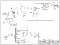
The "Two Stroke Amplifier" is in a book I do not have handy.
The first unofficial schematic I found (attached) does not seem to have a Standby switch?
It sure would be good to show what you built.
However-- some similar plans put an SB switch between the rectifier and the first cap.
When switch is open, the output of the rectifier is all lumpy halves of the AC wave. The expected value of "DC" is 325V*0.9 or 292V, which with un-sag is essentially your 300V. And we do not care! This is not a working condition. That first cap isn't even in the picture.
When switch is closed, we expect 325V*1.4 which is 455V, minus tube-rectifier losses which will generally put you at 400V or 350V. "500V" is not right. Right AT turn-on, this point will tend to rise to 450V, but after 10 seconds as the 6V6 starts to suck it should fall off to the upper 300s.
Attachments
Hello there!!!!,
Problem solved. Multimeter readings are as follow:
B+1: 352V
B+2: 260V
B+3: 165.7
Plate: 334
I rewired the 5Y3, bypass the standby, and change the 68K dropping resistor. I also changed the tube for a KT66. It sounds very healthy now. A real joy to play.
Thank you very much indeed for your comments. You've been very helpful!
Now I'm planning to put a pentode/triode switch... but when I tried I was getting hum (it removes the B+2 filter cap). Let's see if I can manage.
Cheers!!
- Status
- Not open for further replies.
- Home
- Live Sound
- Instruments and Amps
- Voltage issue