Built a power supply based on LM317/LM337 using
fixed resistors. Giving +- 11.3v. But when I connect the PS to the circuit (OPAMP AD8620) the + supply remain 11.3v but the - supply (LM337) drops by 1 v, that is, it shows about -10.3v. What could be the reason? Is it a standard fact about LM337? I have couple of these PS circuits built to check and LM337 shows the same phenomena!
The resistor from output to control pin is 120Ohm in both LM317 and LM337.
Thanks for any comment/reply.
Regards
Roushon.
Last edited:
What is the input voltage to the LM337 with the output loaded?
There should be at least 3V drop across the IC to maintain regulation. Also input and output capacitors are a good idea mounted close to the IC to avoid instability as per the data sheet.
There should be at least 3V drop across the IC to maintain regulation. Also input and output capacitors are a good idea mounted close to the IC to avoid instability as per the data sheet.
Does the negative regulator have a minimum current (check the data sheet) that must be drawn at all times ?
Thanks for all the comments. The input voltage is +-20v, so there is enough difference in voltage. Will check about the minimum current requirement and reduce the output-to-control pin resistor value (and hence the resistor from control to ground also).
Regards
Roushon.
Regards
Roushon.
Just add 1Kohm across the output from each reg to 0v to ensure that the minimum load requirement is met under all conditions.
Just add 1Kohm across the output from each reg to 0v to ensure that the minimum load requirement is met under all conditions.
Great! Thanks a lot. Will do that.
Roushon.
In my experience getting the 'wrong' output voltage has been related to oscillation. Do you have a scope to check for that? The minimum current requirement would in my estimation result in a more negative output voltage being registered, not less - without enough current the magnitude of the output rises.
Last edited:
minimum load
Doesn't the 120 Ohm resistor between Output and Adjust pins take care of the min load? A little more from a 1k to ground won't hurt but I doubt this is the problem with the circuit here.
Just add 1Kohm across the output from each reg to 0v to ensure that the minimum load requirement is met under all conditions.
Doesn't the 120 Ohm resistor between Output and Adjust pins take care of the min load? A little more from a 1k to ground won't hurt but I doubt this is the problem with the circuit here.
Last edited:
In my experience getting the 'wrong' output voltage has been related to oscillation. Do you have a scope to check for that? The minimum current requirement would in my estimation result in a more negative output voltage being registered, not less - without enough current the magnitude of the output rises.
Unfortunately, I do not have a scope. I am a bit confused now. I tried the PS with different circuits (one is a bass boost and the other is a dc- servo, both based on AD8620) which have different layouts and PCB designs. Not sure if both the circuits are oscillating. The final amp output is silent and clean. Will do some more experiments and post the result here.
Regards
Roushon.
Have you used the 2 x diodes in each + and - circuit as recommended in the datasheet.
It is a known problem that if they are not used one regulator may start up before the other and strange things happen.
The common way to ensure that each regulator has it's minimum load is with a small resistor and an LED, the LED doubles up to tell you supply is ON.
It is a known problem that if they are not used one regulator may start up before the other and strange things happen.
The common way to ensure that each regulator has it's minimum load is with a small resistor and an LED, the LED doubles up to tell you supply is ON.
these "adjustable" 3pin regulators require a voltage reference.
The tolerances of the voltage reference and the tolerance of the regulators internal 1.25V add up to a considerable and random variation in the final output voltage.
You need to "adjust" your external voltage reference to give the "close enough" output voltage.
Vout = 1.25(+-tolerance) * [Resistor lower (+-tolerance) / Resistor upper (+-tolerance) +1]
Again, the AD8630 only draws 2.5 to 3mA from the supply rails. These regulators need a passive load (added resistor) to meet the minimum load requirement.
Note LM337 is not a true complement to the LM317. It can be treated the same, but it does behave slightly differently. I've found it responds better to a higher minimum load current, 10mA++, and it IS more sensitive thna the 317 to missing the reverse-polarity protection diodes esp. if you use large Cadj caps.
Mirlo-
Doesn't the 120 Ohm resistor between Output and Adjust pins take care of the min load? A little more from a 1k to ground won't hurt but I doubt this is the problem with the circuit here.
It can do, but it is not the way to get best ripple-rejection performance from either LM317 or 337s. Set R1 around 1K instead, use R2 to set the output voltage and bypass it with at least 10uF. Then use an additional load resistor to 0v from the output to guarantee the minimum load requirement of 10mA is achieved. It costs you pennies - one resistor per supply - and separates the two issues.
AndrewT:
"...You need to "adjust" your external voltage reference to give the "close enough" output voltage.
Vout = 1.25(+-tolerance) * [Resistor lower (+-tolerance) / Resistor upper (+-tolerance) +1] ..."
You forgot the ~100uA of current from the ADJ pin.
martin clark:
"...Set R1 around 1K instead ..."
Not really, you want to have a large (relatively) amount of current to swamp the variation in the ADJ pin current.
When the ADJ pin current changes slightly there will be less change in the output voltage when using lower resistances.
🙂
True - my point was, these are effectively 1.25v regulators 'standing' on whatever you put between the Vadj pin and 0v. Use a larger R1 value is directly equivalent to using a larger Cadj decoupling cap - effectively you get a reduced additional noise contribution from the offsetting resistor (or zener) from multiplyng that nominal 1.25v up to your chosen output voltage.
The variation in Vadj pin leakage - well under 10uA - is a very, very small error term and not remotely significant for the DC voltage setting (even R1 = 1k swamps the datasheet 50uA mean by 25x)
The variation in Vadj pin leakage - well under 10uA - is a very, very small error term and not remotely significant for the DC voltage setting (even R1 = 1k swamps the datasheet 50uA mean by 25x)
The circuit
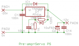
Thanks again for all the discussion. The circuit is attached.
I must do some more reality check before posting.
Still do not understand why should the voltage drop as
soon as I connect the circuit!
Regards
Roushon.
Thanks again for all the discussion. The circuit is attached.
I must do some more reality check before posting.
Still do not understand why should the voltage drop as
soon as I connect the circuit!
Regards
Roushon.
Attachments
Last edited:
perhaps the 337 is connected wrong, pin2 input.....pin3 output?
+1
Certainly .....TO-220 versions the input and output pins swop over designation between the LM317 and LM337 .
Its easy...
Test the output voltage with 1k as a load. What is it ?
Test it again with 100 ohm load. Should be identical.
If it is the reg is OK and the opamp circuit is faulty and pulling it down.
If it isn't the reg has a problem or the input voltage is dropping below the regs minimum differential.
Two minutes to test and diagnose 😀
Its easy...
Test the output voltage with 1k as a load. What is it ?
Test it again with 100 ohm load. Should be identical.
If it is the reg is OK and the opamp circuit is faulty and pulling it down.
If it isn't the reg has a problem or the input voltage is dropping below the regs minimum differential.
Two minutes to test and diagnose 😀
Thanks Mooly! Now that I know what to do it is indeed
a two minutes job. About three years back I built the amp
and it is playing well since then. There were several issues
(including the present one) then which I did not care much
(being a beginner was not aware of the dangers). Now
preparing to rectify/upgrade the amp. This weekend I will
open the amp and experiment.
Regards
Roushon.
- Home
- Amplifiers
- Power Supplies
- Voltage drop in LM337 based PS!