Say, folks, here is a dumb problem that I'm not yet able to track down.
I have a simple voltage doubler connected a 240VAC winding. The partially loaded xformer is actually producing 270VAC. The doubler is 1n4007s with 220u/450V caps. I am expecting to get about 750volts (no load except cap leakage) from this configuration. I get more like 715?
When I load the doubler with about 23mA, it pulls way down to 638V or so. The xformer loads down to 260VAC.
This loading effect seems excessive to me. I've run PSUD on it and nothing like this happens.
Is this telling me that my doubling caps are leaking heavily? Or something else?
Thanks.
Runeight,
With 2 ohm ESR caps and 60 ohm transformer resistance, I SIM the results you are measuring.
With 2 ohm ESR caps and 60 ohm transformer resistance, I SIM the results you are measuring.
Hi -
Are you going half wave? Btw, if you go full wave off of a center tapped secondary, you can use a bridge rectifier for all the doubler diodes, I've found. That's how I'm getting a unipolar doubled voltage in addition to the regular plus and minus fw rectified outputs for my HT amp project. I'm getting good regulation results with my doubler & tripler because I'm using polypropylene caps which have negligible esrs. Of course the values are smaller so there's more ripple, but that'll be cleaned up with a series choke/shunt cap filter at the doubler (& tripler) output in the final version.
Btw, if you are running two caps in series at the output of the doubler, maybe adding a couple of high value voltage equalizing resistors might be worth a try?
Thanks. It's a full wave doubler. The secondary is center tapped, but I'm not using the tap.
The doubler caps are followed by a choke and then two caps in series with equalizing resistors in on the caps.
Thoriated, can you show a drawing?
The doubler caps are followed by a choke and then two caps in series with equalizing resistors in on the caps.
Thoriated, can you show a drawing?
Um, that's an awful lot of circuit for a doubler. Reminds me of the dual-bridge circuits oft used in SS amps.. 🙄
There's also a lot of circuit surrounding the key area but look below. This is (er, will eventually be) the power supply for a quad 6146 amp, 600V at .5A. 😱 (The big PT would be either tapped or fed with a buck transformer to provide the three output voltages shown.)
The key is low resistance (winding, ESR and diode losses need to be minimized) and high capacitance (which makes high current peaks which require low resistance...). This style doubler can be envisaged as two half-wave rectifiers working opposite half-cycles from the same two-wire source.
Tim
Attachments
Hi -
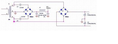
The doubler is in the left half of the schematic, and the choke and second shunt cap are optional, depending on how much ripple is tolerable, so the full wave doubler, aside from the transformer, can be realized with four components. The right half is a conventional dual output supply which is shown only for comparison purposes.
The doubler is in the left half of the schematic, and the choke and second shunt cap are optional, depending on how much ripple is tolerable, so the full wave doubler, aside from the transformer, can be realized with four components. The right half is a conventional dual output supply which is shown only for comparison purposes.
Ok.
The nice thing about a FWB is that, if you go overseas a lot, you need only change one (1) connection (which can be done with an SPST switch) to convert from FWB to FWD! That's how switching supplies get dual voltage capability: they run the HF transformer and stuff from +340VDC rails.
Of course this is moot since you'll smoke almost any transformer or otherwise lose regulation (except maybe with a Turner Audio transformer...damn he overbuilds those things) in doing so. 😉
If nothing else... it might be a good way to test double the voltage on a circuit. I suppose. Not really too useful for audio. 😛
Tim
Hi, Runeight -
Is 50mA the transformer's rating at 240VAC? If so, perhaps its secondary voltage peaks are being flattened when the 23mA load is applied which will show up as a loss of regulation. Is the 23 mA passing through the 5.1K before the point where the output is measured? That could result in 100 + volts of drop, also.
I used a HW circuit to get a bipolar output supply in the early days of my OTL amp but I probably pushed my luck a little bit when I used one of the dual primaries of a 1400VA toroid kit to do so🙂
- Status
- Not open for further replies.
- Home
- Amplifiers
- Tubes / Valves
- Voltage Doubler Problem