This is voltage doubler:
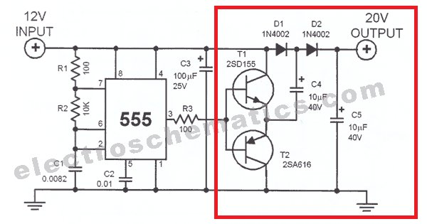
I want to change the circuit in red frame into the circuit below.

I wonder if it needs to add caps in the red circle?
And, is the circuit correct?
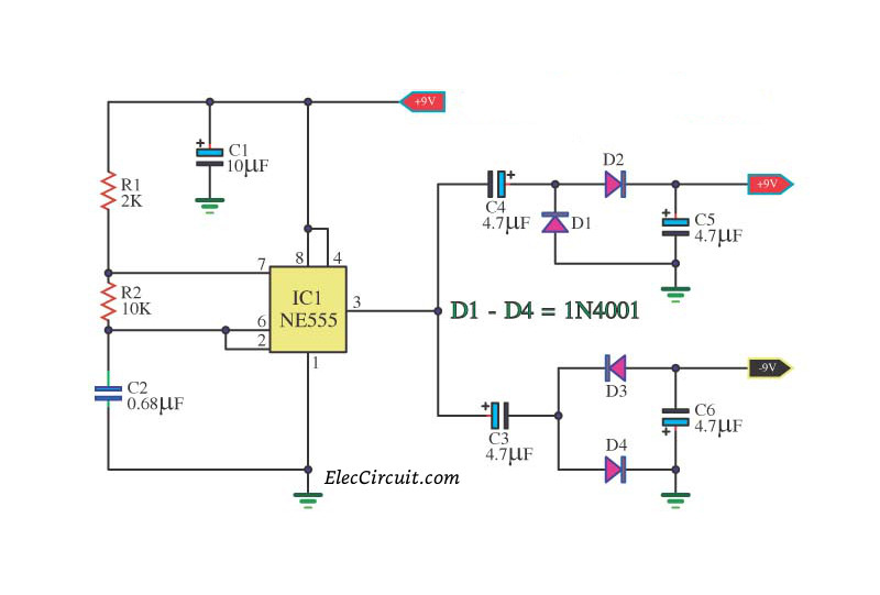
I want to change the circuit in red frame into the circuit below.
I wonder if it needs to add caps in the red circle?
And, is the circuit correct?
Last edited:
If you do, it will no longer work as it will lose the DC element. You can keep on adding doubler diodes and as long as the capacitor values are correct for the frequency, you can triple, quadruple etc the voltage. You could of course use a different polarity on the diodes and capacitors to achieve both positive and negative voltages.
Take a look at some old colour tv eht generators for ideas. That is how they produced the high voltages from a low voltage source. The practice is the same.
Take a look at some old colour tv eht generators for ideas. That is how they produced the high voltages from a low voltage source. The practice is the same.
The circuit will not work. In the positive doubler you need to tie the output capacitor across V+ and GND. In the negative doubler, the red circle need to be tied to GND instead of tied to B+.
So...
1. In the positive doubler, tie the output capacitor across V+ and GND
2. In the negative doubler, the red circle need to be tied to GND instead of tied to B+
And it will work?
1. In the positive doubler, tie the output capacitor across V+ and GND
2. In the negative doubler, the red circle need to be tied to GND instead of tied to B+
And it will work?
So...
1. In the positive doubler, tie the output capacitor across V+ and GND
2. In the negative doubler, the red circle need to be tied to GND instead of tied to B+
And it will work?
I was not saying it would work although it should. My point was it would NOT work if you don't make that two changes.🙂
Sim it, or breadboard and prove it.

circuit in your posts #7 and #8 are not doublers, and you will not see an output voltage greater than 9V. Most op-amps do not have much output current capacity, you might just want to stick with the push-pull drivers shown in your opening post.
It seems to me that in the first post there are two separate mechanisms depicted although they both look like a stacking method.
The positive voltage doubler is a switched capacitor circuit, with C4 being connected in parallel and in series.
C4 is firstly charged to Vs when T2 (PNP) is open (through D1). At the same time D2 charges the output cap, C5, to Vs. This is the
When the pulse goes positive, T1 opens and T2 closes. That way Vs is superimposed through T1 to the bottom pin of C4, thus boosting the voltage to Vs + VC4. This increased voltage is now applied to C5 through C2.
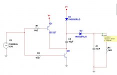
Actually the arrangement is not optimum. There is no reason for the transistors, which act as switches, to be connected in this push-pull arrangement. I got better results with an NPN grounding C4 and a PNP connecting it to Vs.
If switches were used, rather than diodes and transistors, then D1 would also be a switch closing on the positive peak of the pulse.
I attach a schematic.
The positive voltage doubler is a switched capacitor circuit, with C4 being connected in parallel and in series.
C4 is firstly charged to Vs when T2 (PNP) is open (through D1). At the same time D2 charges the output cap, C5, to Vs. This is the
When the pulse goes positive, T1 opens and T2 closes. That way Vs is superimposed through T1 to the bottom pin of C4, thus boosting the voltage to Vs + VC4. This increased voltage is now applied to C5 through C2.
Actually the arrangement is not optimum. There is no reason for the transistors, which act as switches, to be connected in this push-pull arrangement. I got better results with an NPN grounding C4 and a PNP connecting it to Vs.
If switches were used, rather than diodes and transistors, then D1 would also be a switch closing on the positive peak of the pulse.
I attach a schematic.
Attachments
circuit in your posts #7 and #8 are not doublers, and you will not see an output voltage greater than 9V. Most op-amps do not have much output current capacity, you might just want to stick with the push-pull drivers shown in your opening post.
D4 grounds the positive swing of the output - that is almost a short circuit. Unless I am mistaken, a very expensive way to get -9V @ some puny current.
- Status
- Not open for further replies.
- Home
- Amplifiers
- Power Supplies
- Voltage doubler and Negative generator