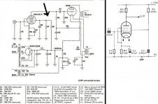
Hello, I'd like to know the reason Western Electric used a voltage divider (VD)in the driver tube (310) in G2 instead of a more standard dropping resistor. The image shows the SP 91 version with divider in R8/R7 (arrow) and standard setup in generic pentode (right).
Although the voltage divider is easy to understand there is an aditional current to ground. How do you manage to calculate Ig2 current regarding the VD. Just trying to understand the circuit well.
Best regards
Roberto luis, Argentina
Although the voltage divider is easy to understand there is an aditional current to ground. How do you manage to calculate Ig2 current regarding the VD. Just trying to understand the circuit well.
Best regards
Roberto luis, Argentina
Attachments
Last edited:
The voltage divider is more stable, voltage level wise, than just a pullup resistor (versus varying screen current). To measure screen current, just subtract the pulldown resistor current from the pullup resistor current. (measure voltages across the resistors, calc the currents from the resistances, subtract to get the difference which departed thru the g2)
Last edited:
Thanks Smoking, quite clear. Apparently it is a try and true method to calculate screen current, modifying VD resistors order of magnitude while maintaining its relationship.
You cannot use the data sheet tables in advance as they use a more standard topology regarding screen grid.
Best regards, Roberto
You cannot use the data sheet tables in advance as they use a more standard topology regarding screen grid.
Best regards, Roberto
- Status
- Not open for further replies.