Oh yes, that's smart!
Fantastic with your illustrations! Thanks!
It looks like, if I replace R1 with a pot or an voltage controlled resistor, I can reduce the current in the circuit?
Fantastic with your illustrations! Thanks!
It looks like, if I replace R1 with a pot or an voltage controlled resistor, I can reduce the current in the circuit?
Last edited:
Okay great! I think that you know where I am targeting🙂
So I can fairly simple let my signal generator send a square wave signal to ("my load project" = MLP) and that will make the switching via Voltage.
Is it possible to make the current current load, variable, i.e. via adjusting a resistor or something, so I can adjust it to 10A, 7A, 1A or what ever I think I need?
You can use a signal generator to drive the switching transistor. A power FET might be best in that case.
Look at the diagram in post #11
If you feed the generator into the opamp input and vary the amplitude (so a volume control in from of the opamp) then the current should be variable.
The opamp needs to be one that would work on a single supply and allow the inputs and outputs to go down to ground potential.
Oh yes, that's smart!
Fantastic with your illustrations! Thanks!
It looks like, if I replace R1 with a pot or an voltage controlled resistor, I can reduce the current in the circuit?
You could alter R1 but there is a big problem doing so... and that is because it passes the full load current.
A pot (if you could find a low value one) could not handle that current.
So we change the reference voltage on the Zener instead if we want to alter the current.
Ok so that's a great current source with variable current. 🙂
I understand that the power supply is loaded by that circuit, would that power supply be "tested" by 10A if I chose to led the circuit deliver CC of about 10A?
I understand that the power supply is loaded by that circuit, would that power supply be "tested" by 10A if I chose to led the circuit deliver CC of about 10A?
10 amps is a lot, you would need a suitable transistor for that. If that is what you want then yes, its perfectly do-able with the correct parts.
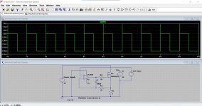
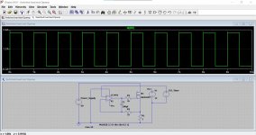
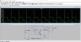
Here is the other circuit. If we vary the input voltage of the switching signal we vary the constant current drawn. So all you need is a 'volume control' on the output of your generator and a way to know the amplitude you are applying.
This shows the input squarewave at 1 volt (and the current is 1 amp) and at 3.3 volts (current is 3.3 amps) and 0.05 volts so on.
It works really well. Ignore those spikey glitches, they will be artefacts of the simulation.
Attachments
- that is still CC mode, just with transient.You want to test a power supply, you select 10A CC
After that do you select 1A CC and you keep switching between these two values, as fast you can, to test how your power supply react to suddenly current spikes.
That is clearly CC-mode. Constant current. Just only with capability of fast transients. Electronic load circuits are usually voltage controlled by definition.In short signal generator sends 1V to your electronic load, and your diy electronic load sets CC to 1A. Then do your signal generator send out 10V and your electronic load do set CC to 10A.
Hope that's more clear?
Look here, for example.
Last edited:
Okay thanks for finding the right word for that. My electronic load is of the type, that you push off, change the CC and turn it on again. If you in any way wich to change the CC value, do you have to push off again and change the value. Almost useless for testing current spikes.
Am I right in understanding that by selecting C, I can then let the transient change like i.e. a sinus curve, with short spikes or maybe stepping up and down. All with the possibility to set duration and frequency?
Am I right in understanding that by selecting C, I can then let the transient change like i.e. a sinus curve, with short spikes or maybe stepping up and down. All with the possibility to set duration and frequency?
It may be useful Electronic Load Fundamentals.pdf (It is may be not the best explanation but at least.)
Last edited:
Thank you! I'll try to read it. 🙂
I think that Mooly's circuit, combined with some more knowledge will put me in the right way.
I think that Mooly's circuit, combined with some more knowledge will put me in the right way.
- it can be useful if it has short edges (fast falling or fast rising edges) between 'on' and 'off' states (and if you have a digital osc.). So if it turns on and off fast - you don't need anything else (except digital oscilloscope to catch that transient).My electronic load is of the type, that you push off, change the CC and turn it on again. If you in any way wich to change the CC value, do you have to push off again and change the value. Almost useless for testing current spikes.
Yes, he gives you a basic (simple) electronic load circuit to start with. That links I gave you - it is real world powerful prototypes. They are a bit over-complicated to what you need.Thank you! I'll try to read it. 🙂
I think that Mooly's circuit, combined with some more knowledge will put me in the right way.
Sorry for my slow answer, suddenly had lots of stuff to take care of! 🙂
To avoid having to build some sort of advanced programmable load pattern, did I think, why not just let the signal generator, create the pattern and thereby adjust the amount of load. "All I needed" was a Constant load that, live, could be changed by input voltage.
In short a CC-value and CV-value that could be changed live, depended on a input signal from the signal generator.
This May sounds crazy so please don't be annoyed..
@FriedMule
Try a Light bulb.. it gives you all what you want.It gives you constant current because when you change the Supply Voltage changes, the bulb goes darker or brighter, so current and also Voltage Changes..
Then using some High Voltage High Ampere Diodes to keep the UNIT under TEST out of your Control Cirquit and also your control Cirquit out of the device under test , so then with two Amp Meters and one or two Voltmeters you could see the change. At least this is what I understood of your Question..
If its that what you are looking for..
Hope whatever you design that it will work out. And if I'm to far off the real thing nothing has been broken, was just a thought.
Regards Chris
As I understand you want to control the variable load resistor (connected as a rheostat) by an external voltage. Then you apply this load to a constant voltage. By changing the resistor, you will change the current flowing through it.
Alternatively, by connecting the variable resistor as a potentiometer, you will get variable voltage on the slider terminal.
The shaft of the variable resistor has to be rotated by a servo, which in turn is controlled by the input voltage.
Alternatively, by connecting the variable resistor as a potentiometer, you will get variable voltage on the slider terminal.
The shaft of the variable resistor has to be rotated by a servo, which in turn is controlled by the input voltage.
Electronic Load PCB
DIY Electronic Load PCB Kit for Testing Power Supplies - FiveFish Audio
http://fivefishaudio.com/pdf/EloadAssemblyGuide.pdf page 11
Inject control voltage where I put the red arrow. The MOSFETs will try to suck Current at the rate of 1mA/1mV. The upper limit is not stated? But it supports "several Amps" so you inject up to several Volts.
This is of course Mooly's #11 sketch dressed-up as a thing you can buy/build.
Attachments
- Home
- Design & Build
- Construction Tips
- Voltage dependent load?