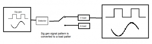
I have now tried to draw a image on what I try to make.
Here did I chose a signal generator, but it could also be any other Voltage source.
The signal generator makes a signal, i.e. a sinus curve from 0.1V to 2V.
The detector registers the Voltage each u / m second or something
The switch let me decide if I am interested in VC (Variable current instead of CC) or VV (Variable Voltage, not CV).
End result is a load that adjust the load in a value, decided by the sig gen's input voltage.
In short, image you had a CC load connected to a battery or psu. On this load can you "live" turn on the button to change the "CC". Just instead of me having to turn on anything, will I let a signal gen do it for me.
Attachments
Last edited:
🙂 I'd have to think about that...
So we have a variable output signal source. A signal generator or even an amplifier output
If you look at a signal quickly enough (lots of time a second) you just see the original signal. If you look at it infrequently then it could be anywhere in value over its cycle.
I think you mean you need an average DC level related to the amplitude... maybe 🙂 That means you need a rectifier, an active rectifier that has no volt drop and that covers the full frequency range. That would give a DC voltage related to the signal amplitude.
Switches are easy. Mechanical if manually operated or it can be a relay or an electronic switch.
You can use the average DC value from the rectifier to operate a comparator or a series of comparators (like an LED VU meter) where each output switches a different load value into circuit.
(Making loads constantly variable and not fixed in value would be hugely challenging to do it well)
The signal generator makes a signal, i.e. a sinus curve from 0.1V to 2V.
So we have a variable output signal source. A signal generator or even an amplifier output
The detector registers the Voltage each u / m second or something
If you look at a signal quickly enough (lots of time a second) you just see the original signal. If you look at it infrequently then it could be anywhere in value over its cycle.
I think you mean you need an average DC level related to the amplitude... maybe 🙂 That means you need a rectifier, an active rectifier that has no volt drop and that covers the full frequency range. That would give a DC voltage related to the signal amplitude.
The switch let me decide if I am interested in VC (Variable current instead of CC) or VV (Variable Voltage, not CV).
Switches are easy. Mechanical if manually operated or it can be a relay or an electronic switch.
End result is a load that adjust the load in a value, decided by the sig gen's input voltage.
You can use the average DC value from the rectifier to operate a comparator or a series of comparators (like an LED VU meter) where each output switches a different load value into circuit.
(Making loads constantly variable and not fixed in value would be hugely challenging to do it well)
I think FriedMule means something that can be switched between being a voltage-controlled current source and a voltage-controlled voltage source, in both cases designed such that it can draw current from an external supply. That means that the voltage-controlled voltage source would basically be a shunt regulator.
You could use such a thing to apply current steps or voltage steps to a power supply under test to see the step response of its voltage control loop or its current limiting loop, respectively. That only works well if the response of the voltage-controlled current source / voltage-controlled voltage source is well-damped and fast compared to the power supply under test.
You could use such a thing to apply current steps or voltage steps to a power supply under test to see the step response of its voltage control loop or its current limiting loop, respectively. That only works well if the response of the voltage-controlled current source / voltage-controlled voltage source is well-damped and fast compared to the power supply under test.
Thanks Marcel 🙂 Yes it could be... perhaps that is all he wants.
I did something along those lines but just using a fixed resistor switched by a FET in the LT tutorial thread. Posts #71 and 72 and surrounding area.
Installing and using LTspice IV (now including LTXVII). From beginner to advanced.
I did something along those lines but just using a fixed resistor switched by a FET in the LT tutorial thread. Posts #71 and 72 and surrounding area.
Installing and using LTspice IV (now including LTXVII). From beginner to advanced.
Sorry for my slow answer, suddenly had lots of stuff to take care of! 🙂
A normal electronic load has normally Constant Current and Constant Voltage, among other things. None of these load-sittings shows what would happen if, let's say, an amplifier suddenly do demand lots of Voltage or current due to the dynamic in the music.
Also non of these load-settings, shows you how a power supply would react if things goes into clipping for a short moment. All that a load can show is how things will react if things are constant with no change in a while.
I want to be able to simulate a speakers load on the circuit, test when ripples can occur and yes, how a circuit do react when things are working when things are not constant but changes in a few mS.
To avoid having to build some sort of advanced programmable load pattern, did I think, why not just let the signal generator, create the pattern and thereby adjust the amount of load. "All I needed" was a Constant load that, live, could be changed by input voltage.
In short a CC-value and CV-value that could be changed live, depended on a input signal from the signal generator.
...an amplifier suddenly do demand lots of Voltage or current due to the dynamic in the music...
This is a most confusing sentence. An amplifier doesn't demand voltage. It provides voltage to a load and operates from the voltage provided by the power supply. 😕
What changes is the current required by the load due to the change in the voltage at the output of the amplifier, a requirement passed along to the power supply and which could cause the voltage provided to sag.
Or are trying to simulate back emf ?
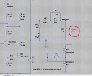
Here is my amplifier that you are building. There is an 8 ohm load attached permanently and also a 3 ohm load that is connected every few milliseconds across the 8 ohm load.
So the amplifier output voltage falls when the low ohm loading is present... now can you see why by looking at the amplifier circuit why it falls so much?
We could also look at power supplies in the same way.
You could make the switch voltage operated so that when the input signal passed a certain level it closed the switch but that wouldn't really tell you much because the input voltage wouldn't be a constant anymore.
So why with my amplifier does the level fall so much with low impedance loading?
Attachments

00940 Yes sorry for my lack of language skills in the electronic world.
Let me say it in an other way. Your amplifier has a rail to rail voltage and if you decide to play to laud, do the amplifier start to clip or you can have a speaker that have an impedance of maybe down to 2 Ohm for a short while, also not great. 🙂
These circumstance could you easily test by using using some resistors and by simulating a dynamic current usage.
I do not think I have found any way to change the impedance live,like a speaker do.
About dynamic voltage, lets say I am building an alarm, one where a circuit is turned on if the alarm triggers. How would the power supply react by suddenly getting that circuit added to it's workload?
I would like to be able to change the ammound of Voltage load and Current load, but instead of having to switch of the load, input new load-values and then turn on the load again, do I want to let my signal generator do it, and it outputs Volt.
Mooly I do really appropriate how much work you put into teaching me! Yes your explanation makes a lot of sense!
Sins a dynamic current load is not sold on the marked, like the CC and CV are, how do one find out how a circuit do react by suddenly changing values?
Sins a dynamic current load is not sold on the marked, like the CC and CV are, how do one find out how a circuit do react by suddenly changing values?
If you are interested in the interaction between power supply and amplifier, music, and speaker load.... why not connect an amplifier and dummy-load to your power supply and play music through it??
It does not really have to be THE amplifier you will use, just something similar.
A dummy resistor is not a loudspeaker but the general idea of loudspeaker impedance ratings is that the speaker will not be a "worse" load than the resistor.
Or just copy plans/parts which have proven satisfactory for the job.
You can over-complicate much more, after you gain experience.
I can of cause find out on how low an impedance a driver / speaker goes to and connect resistor to the amplifier, but that do only tell me on how the amp will react if the speaker had a constant insane impedance. And it will heat up the amp in an unrealistic way.
I thought, why not make a load that can change impedance, up an down while testing the amplifier.
I know you could program some user interface on an adorino, make that change some values and adjust a circuit. But why make it so complicated?
A simpler solution would be to let input voltage, control the load. So 2V in would give 2A load and so on.
A simple construction that act as an "op-amp" could try to force input and output to be the same. To do that will it "demand" current / voltage from second input, and thereby let second input act as a load.
There have to be a simple way to adjust resistance by voltage input, so that the end result is that 2V in, lowers the resistance so 2A goes trough the resistor. 🙂
A load that changes impedance is usually something that changes its impedance as the frequency changes, not the voltage.
A speaker changes its impedance with frequency, not voltage. It has the same impedance at 1 volt, 5 volts or 10 volts.
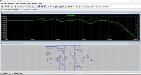
Again, my amplifier with a simulated reactive load. This is my B&W speaker. Look how the output (the voltage across the speaker) varies with frequency.
As I asked before. Can you see why it does that? Why is it not flat? Is the amplifier not good or is there another reason 🙂
The circuit in that box representing the speaker is shown in full. That is a complex load impedance.
A speaker changes its impedance with frequency, not voltage. It has the same impedance at 1 volt, 5 volts or 10 volts.
Again, my amplifier with a simulated reactive load. This is my B&W speaker. Look how the output (the voltage across the speaker) varies with frequency.
As I asked before. Can you see why it does that? Why is it not flat? Is the amplifier not good or is there another reason 🙂
The circuit in that box representing the speaker is shown in full. That is a complex load impedance.
Attachments
Thanks Mooly, yes it's somewhat clear🙂
B&W speakers?! Wow someone like quality and great sound! 🙂
The reason for me keeping talking about Volt, is that a signal generator do make change and patterns in Volt, not current. So if I want to let a signal generator, control the load circuit, the circuit has to look at Volt, not current. What the circuit then do with that info, is then up to how it's build.
🙂 , Every new post you make things more unclear then it was in previous your post.Also non of these load-settings, shows you how a power supply would react if things goes into clipping for a short moment. All that a load can show is how things will react if things are constant with no change in a while.
I want to be able to simulate a speakers load on the circuit, test when ripples can occur and yes, how a circuit do react when things are working when things are not constant but changes in a few mS.
I may wrong but I think you want to make something overcomplicated.
I do not know how to explain it but I'll try to cut it to the bone, forget all other comments I have wrote before. 🙂
Imagine a basic standard electronic load, one you can build yourself.
You want to test a power supply, you select 10A CC
After that do you select 1A CC and you keep switching between these two values, as fast you can, to test how your power supply react to suddenly current spikes.
After getting tired of doing that, do you ponder on a way to do it automatically.
Sins the signal generator can be set to output 10V and 1V, do you build a circuit that read the voltage and adjust your diy electronic load, maybe via a simple voltage controlled pot.
Now can you just tell the signal generator to put out some square or sinus signal in Volt and your diy electronic load, changes it's CC load.
In short signal generator sends 1V to your electronic load, and your diy electronic load sets CC to 1A. Then do your signal generator send out 10V and your electronic load do set CC to 10A.
Hope that's more clear?
Imagine a basic standard electronic load, one you can build yourself.
You want to test a power supply, you select 10A CC
After that do you select 1A CC and you keep switching between these two values, as fast you can, to test how your power supply react to suddenly current spikes.
After getting tired of doing that, do you ponder on a way to do it automatically.
One step at a time. This one is easy.
You make a constant current sink which can be as simple as two transistors or one single transistor and a Zener or LED.
To make it automatic to see how the power supply reacts you have a simple oscillator (like a 555 timer chip) to switch a different value part in and out of the current sink. That changes the current flow.
So the power supply under test is now loaded by two changing current values and you can look on a scope and see how it reacts, or if you run it slowly enough you can look on a meter and see the voltage change in the power supply.
How fast it switches depends on the oscillator speed.
🙂
That sounds great, but the two values it jumps between can then only be changed by adjusting a pot or by resoldering some components and the frequency it switches, is also depended on the 555?
If we take one step ad a time🙂
can that circuit be triggered by external voltage instead, maybe on or off?
If we take one step ad a time🙂
can that circuit be triggered by external voltage instead, maybe on or off?
The two values are fixed by the initial design. You would choose values that gave you the two currents you wanted.
Another transistor would then switch one of those values into the circuit to change the current value.
That switching is done by a voltage... that come from the oscillator. For example a logic 0 or 1 or for a 555 timer it could 0 volts and 12 volts.
Another transistor would then switch one of those values into the circuit to change the current value.
That switching is done by a voltage... that come from the oscillator. For example a logic 0 or 1 or for a 555 timer it could 0 volts and 12 volts.
Okay great! I think that you know where I am targeting🙂
So I can fairly simple let my signal generator send a square wave signal to ("my load project" = MLP) and that will make the switching via Voltage.
Is it possible to make the current current load, variable, i.e. via adjusting a resistor or something, so I can adjust it to 10A, 7A, 1A or what ever I think I need?
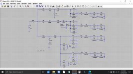
Here is a simple current sink switched by a timer. This gives just one value which is the starting point. You can see the current in the transistor is the same whether the power supply is at 10 volts or 60 volts. Its a constant current load.
Attachments


- Home
- Design & Build
- Construction Tips
- Voltage dependent load?