Is it possible to build a load that mirror it's load to an input and multiply by 10?
Lets say I send 1V into the "sense" part of the circuit and that make the load, load 10V or by switching, 10A from a secondary power supply?
Lets say I send 1V into the "sense" part of the circuit and that make the load, load 10V or by switching, 10A from a secondary power supply?
That sounds like a simple amplification exercise.
You send 1V into something that gives 10 volts out. Loads aren't measured in volts though.
So maybe I don't understand what you are trying to do 🙂
You send 1V into something that gives 10 volts out. Loads aren't measured in volts though.
So maybe I don't understand what you are trying to do 🙂
Thanks for your fast reply.
What I am trying to make is a load, you know that you can get a electronic load to load constant voltage, constant current and so on. I would like to try to build a load where I can change the load by change voltage input.
What I am trying to make is a load, you know that you can get a electronic load to load constant voltage, constant current and so on. I would like to try to build a load where I can change the load by change voltage input.
OK, I think I understand you. Not easy to do well with fine control.
A load is normally something that draws draws current like a resistor. So you could have for example a 100 ohm load, a 50 ohm load and a 10 ohm load where each value is switched by an external voltage. That is pretty easy to do.
You can have as many 'steps' or values of load as you want and all controlled by a voltage that changes between two set limits.
That sort of load is floating and works with AC or DC.
A constant current load that is switchable between values is possible using a similar technique but would normally be usable for just one polarity of voltage.
Mooly so I can adjust VAC and VDC but "only" ADC?
It would be fine for my demands, I was hoping to use it to make "jump" in the load, to test how a psu or circuit will react, a sort of ripple / stress test.
It would be fine for my demands, I was hoping to use it to make "jump" in the load, to test how a psu or circuit will react, a sort of ripple / stress test.
If you use a switched resistor for a load then it will work with DC or AC. So you could test a power supply of any polarity or even put it on the output of an amplifier and see how it reacts to a changing load.
If it is just a DC power supply you want to test then you can switch a load with transistor instead of a relay.
You could also replace the resistor with a switchable current sink to draw a fixed current load irrespective of the output voltage of the power supply.
If it is just a DC power supply you want to test then you can switch a load with transistor instead of a relay.
You could also replace the resistor with a switchable current sink to draw a fixed current load irrespective of the output voltage of the power supply.
Great and if I add a pot to the fixed current load, it could be variable or even a voltage dependent resistor?
You can make a variable current load but it is not a voltage dependent resistor, that's something totally different 🙂
Yes, but what I meant was, if I in some way could adjust the current by the input voltage.
Just like the resulting Voltage load is adjusted by the Voltage. 🙂
Just like the resulting Voltage load is adjusted by the Voltage. 🙂
LOL yes.-)
May I ask on how I multiply by 10?
I mean the voltage load / the current load?
Is it possible?
May I ask on how I multiply by 10?
I mean the voltage load / the current load?
Is it possible?
Yes, you just alter the 1 ohm to get a different ratio of control voltage vs current.
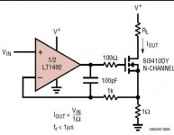
Design a Simple Constant Current Sink Circuit using Op-Amp
Design a Simple Constant Current Sink Circuit using Op-Amp
Yes sorry, what I meant was, is it possible to have i.e. 10x volt and then just flip a switch to 10 x current?
I know ohms law but do a voltage depended resistor not demand some sort of "calculation" circuit?
Lets say I go from 1V to 2V or in load from 10V to 20V.
I know ohms law but do a voltage depended resistor not demand some sort of "calculation" circuit?
Lets say I go from 1V to 2V or in load from 10V to 20V.
It is not a voltage dependent resistor, that is something totally different and not something you could easily make an electronic equivalent of.
The circuit posted allows a constant current to flow in a load, and the value of the current depends on the input voltage to the opamp.
So by adding either gain or attenuation to the control voltage you could for example make a 0 to 10 amp current sink that is controlled by a 0 to 1 volt or a 0 to 100 volts or even a 0 to 10 millivolt control signal.
Do you see 🙂
When you are talking about constant current then saying '10 to 20 volt' doesn't really mean much. The current is the constant, while the voltage depends on external factors such as the value of voltage applied to the load.
yes the current part is just as you say, I am sorry for my bad english and abusing your time in that way. What I tried to say was, now have you provided me with a great way to adjust the current, depended on input voltage.
Now do I try to figure out the voltage load part. As you write about in Voltage dependent load? I did use the wrong word "voltage dependent resistor" sins it's a component, I meant a voltage dependent potentiometer. I can understand that I can chose to makes steps in 1V step or 1uV or whatever, dependent on how insane I would like to be? 🙂
Now do I try to figure out the voltage load part. As you write about in Voltage dependent load? I did use the wrong word "voltage dependent resistor" sins it's a component, I meant a voltage dependent potentiometer. I can understand that I can chose to makes steps in 1V step or 1uV or whatever, dependent on how insane I would like to be? 🙂
yes the current part is just as you say, I am sorry for my bad english and abusing your time in that way................
It's no problem 🙂 I just can't really visualise what you are trying to do or trying to test, that's all.
Do you mean switching between "Constant Voltage mode" and "Constant Current mode"? Or CR and CC?Yes sorry, what I meant was, is it possible to have i.e. 10x volt and then just flip a switch to 10 x current?
I'm afraid, I still can't understand what you want 🙁
CC and CR modes are easy to implement. (CR is constant resistance mode).
The only hard is to implement CP mode - it needs some more parts.
Last edited:
- Home
- Design & Build
- Construction Tips
- Voltage dependent load?