I replaced the outputs and output drivers Also replaced all power supply fets...
Amp is producing Rail voltages but not regualted voltages
I replaced the regulators but still nothing...
Heres what i get on the 494 are theese correct or is the amp in protection?
Pin 1:3.92
Pin 2:4.96
Pin 3:0.06
Pin 4:0.10
Pin 5:1.52
Pin 6:3.45
Pin 7:0.00
Pin 8:13.85
Pin 9:4.80
Pin 10:4.80
Pin 11:13.85
Pin 12:13.09
Pin 13:4.96
Pin 14:4.96
Pin 15:4.96
Pin 16:0.92
This IC only controls rail voltage. Regulators sometimes have dedicated power supplies but most take power from the rails or from windings on the main power transformers.
If you have any more questions, post a photo of the board.
If you have any more questions, post a photo of the board.
I will be posting pics up within the next 5 mins since i still cant get the amp to produce regulated voltages
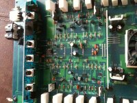
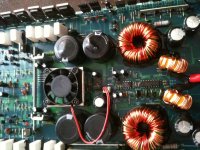
The regulators are likely the two devices on the heatsinks near the fan. Do you have voltage on the large green resistors?
If i use the ground termianl as reference ..
On 1 side of the resistors I get 49 volts of rail
On the other side of them i get 0.8 volts
And on 1 measured directly across it i get 49 volts
Other 1 i get -49 volts
On 1 side of the resistors I get 49 volts of rail
On the other side of them i get 0.8 volts
And on 1 measured directly across it i get 49 volts
Other 1 i get -49 volts
They both get very hot..
They measure 0.558K ohms
I believe they are 560 ohms color bands are Green ,Blue,Brown,Gold
They measure 0.558K ohms
I believe they are 560 ohms color bands are Green ,Blue,Brown,Gold

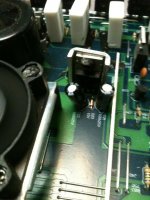
Do the emitters of those two transistors go to the power supply pins of the op-amps?
Can you post a tighter shot of both sides (front/back) of one of the transistors?
Can you post a tighter shot of both sides (front/back) of one of the transistors?
I will charge my camera and get better pics..
The Rail caps are fine its just the plastic dome on top that makes them appear swollen
The Rail caps are fine its just the plastic dome on top that makes them appear swollen

With the zeners back in the circuit, what is the DC voltage on all 3 legs of each of the regulator transistors?
After reoving the transistors heres what i get..
TIP42C
Pad 1:-16.06
Pad 2:-49.9
Pad 3:-0.8
TIP41C
Pad 1:14.25
Pad 2:48.4
Pad 3:-0.8
TIP42C
Pad 1:-16.06
Pad 2:-49.9
Pad 3:-0.8
TIP41C
Pad 1:14.25
Pad 2:48.4
Pad 3:-0.8
- Status
- Not open for further replies.
- Home
- General Interest
- Car Audio
- Volfenhag ZX 7180