Thanks mod team. Appreciate the removal. It's a habit us old timers don't even think about. I'm sure it's much better to keep it more secure from opening up malicious stuff. Won't put it on site again. Sites got alot of knowledgeable helpful participants. Thanks again MichaelMichael,
We discourage people posting their email addresses on the forum. I hve removed many of yours. Please save me the effort.
dave
diyAudio moderation team

This should answer a lot of questions about labyrinths.
https://www.diyaudio.com/forums/subwoofers/322418-17-foot-pipe-sub-12-230-hz-5db.html
My tall cabinet is sectioned into three individually shaped pipes (yes, I know that must feel funny to some... but it shouldn't). I didn't use corner reflectors because I felt it was better to smear the length a bit (reflectors act to make the path length more uniform; yes, I know that must feel funny to some....).
B.
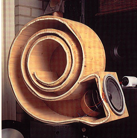
Ben’s 17 foot pipe. A Labyrinth. Not a TL really (an overlong half-wave TL), tuned far to low for anything other than absorbing the entire back wave. Big, probably effective, and completley off-topic to the OPs inquiries. Not a whole lot differnt than putting it in the wall and using the outside (or another room) as the enclosure.
He keeps touting it, but it is no different in concept than the Nautilus.
dave
He keeps touting it, but it is no different in concept than the Nautilus.
dave

That took alot of work to bend and build. Good work. New to transmission design so I always think out side the box. Pun intended. Only built one small 3 foot pair to give a home to some cheap 3.5 " B3N I hade for years and played with but now they have a home. Vented at Voigt design on top because one was built that way and to me opened up the sound, so vented the other. Sound ok for $25 drivers. Really think this is the best design to get alot out ofa driver with out covering up what it has to offer with x overs components and boxed in sound designs. Open and airy for how cheap and small. Cabinets are really easy to build and twerking is easy with fill input or omission through large bottom port. Did you like the sound of the Natalie ie. Snail design. Have you tried a smaller length of tube. It all about thinking different that what has already been done. Any one can play it safe and do what you know is going to work. EXPERIMENT ON. Michael
Last edited by a moderator:
I only ever heard the original 801. It was OK.
Have built midTLs, but i usually do quarter-wave aperiodic.
dave
Have built midTLs, but i usually do quarter-wave aperiodic.
dave
Overlooking your violation of forum rules about personal attacks, I was responding with a link which contained relevant evidence esp on damping. Dave, you seem to have overlooked the post "Think playing around with cavity stuffing might be interesting. Most designs say to damp the interior walls"?Ben’s 17 foot pipe. A Labyrinth. Not a TL really (an overlong half-wave TL), tuned far to low for anything other than absorbing the entire back wave. Big, probably effective, and completley off-topic to the OPs inquiries. Not a whole lot differnt than putting it in the wall and using the outside (or another room) as the enclosure.
He keeps touting it, but it is no different in concept than the Nautilus.
There is no special magic adhering to a textbook prototype. Builders may like it because the theoretical expectations are worked out. At least theoretically.
B.
Hey all ,. Maybe everyone should lighten up a bit and just have some ofun not middle school actions. Nobody should feel belittled EVER. Just f ing be nice. It's not that hard and o whole lot of fun Michael
To clarify:
Having a positive taper (like voigt) will increase the frequency of the fundamental quarter wave, and lower the Q. Having a negative taper like IMF transmission lines say 1->0.25 cross section will lower the fundamental so it correspond to a straigh pipe about 40% longer!
The Voigt pipe use a constriction at the open end this will reduce the increase in resonans frequency causes by the postive flare of the pipe. The driver is also situated 1/3 lenght away from the closed end. This reduce the exitation of unwanted harmonics (costing a bit of radiation resistance at the fundamental)
Several modern transmission speakers also place the bassdriver some way away from the closed end to reduce the problem of unwanted harmonics. Usually at 1/5 of the total length.
The first sentnce is somewhat confusing to me.
A voigt-style taper will need to be longer than a straight pipe to have the same fundemental and the train of resonances lowers in frequency.
A TL taper will need to be shorter than a straight pipe to have the same fundemental and the train of resonances rise in frequency.
Further it hs been shown that a Voigt benefits dramatically from a restricted terminus (mass loading) and with that the optimum driver Zd is about 50%.
Optimum position of the driver depends on the geometry of the line. ⅓ is an approximation for a non-mass loaded Voigt. As an example look at MJK’s table in his paper on nonML quarter-wave lines without jis modeler.
dave
Hey Dave and Dr Boar, you both know way more than most about speaker harmonics including me. The Voigt concept intrigued me so I haphazardly built a small 3.5 foot pair with tiny sort of full range drivers I got on clearance years ago. B3N HI VI. One had an extra slit vent at top of tapper. Mother closed. After listening I cut same vent slit on other cabinet. It "seemed to" open up an overly boxed in sound to me. They sound way better than in sealed or ported that I tried previous. Surprised me how lively and airy for such a cheap small driver!. Will make another build with higher end full range. I imagine with so many design parameters that alto of listen and twerking is needed. Design offers alot of flexible options with fill and amount of it because of access through large vent. Have fun thanks both for additional information. Always helpful to get others insight. Have fun Michael
Last edited by a moderator:
Hi all!
Am new to speaker design as I've only ever built kits in the past.
Like many before me, the TechIngredients Voigt pipe youtube video piqued my interest in Voigts.
Unfortunately, no frequency response graphs were published for it and so I decided to try and model it to see what it might be like.
I am new to hornresp and would like some guidance on whether I have set it up correctly. Based on the thread "Voigt Pipe Design", I used direct radiator, transmission line, offset port, 3 segment, parabolic in input wizard.
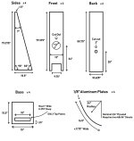
Attached is my exported Hornresp record. I have also attached the driver spec sheet, and the speaker diagram from TechIngredients.
There's a missing dimension regarding the height of the port. And rather than using 9.75" for the port width, I decided to use 10.625". I assumed the height of the port to be half the width of the port, hence in my sim the port is 27cm x 13.5cm.
I tried to draw the internal cavity within the cabinet walls in order to calculate the areas at the different sections. S1 = 1.9cm x 27cm, S2 = 21.4cm x 27cm and S4 = 37.5cm x 27cm.

I've no idea how to set L34 hence don't know what the right S3 would be. In the attached record, L34 is equal to half the port height. But doing so makes the schematic diagram look like the port extends beyond the "horn"?

In any case, what my input is like right now is:

Any guidance on how I can improve my inputs would be much appreciated! 🙂
Am new to speaker design as I've only ever built kits in the past.
Like many before me, the TechIngredients Voigt pipe youtube video piqued my interest in Voigts.
Unfortunately, no frequency response graphs were published for it and so I decided to try and model it to see what it might be like.
I am new to hornresp and would like some guidance on whether I have set it up correctly. Based on the thread "Voigt Pipe Design", I used direct radiator, transmission line, offset port, 3 segment, parabolic in input wizard.
Attached is my exported Hornresp record. I have also attached the driver spec sheet, and the speaker diagram from TechIngredients.
There's a missing dimension regarding the height of the port. And rather than using 9.75" for the port width, I decided to use 10.625". I assumed the height of the port to be half the width of the port, hence in my sim the port is 27cm x 13.5cm.
I tried to draw the internal cavity within the cabinet walls in order to calculate the areas at the different sections. S1 = 1.9cm x 27cm, S2 = 21.4cm x 27cm and S4 = 37.5cm x 27cm.
I've no idea how to set L34 hence don't know what the right S3 would be. In the attached record, L34 is equal to half the port height. But doing so makes the schematic diagram look like the port extends beyond the "horn"?
In any case, what my input is like right now is:
Any guidance on how I can improve my inputs would be much appreciated! 🙂
Attachments
- Home
- Loudspeakers
- Planars & Exotics
- Voigt transmission principle