Michael here ,. Love the old school Voigt transmission design. Huge easy ways to deminish driver misbehavure. Less xover parts or usually none if single driver. Lots of good ones now! Forget phase alignment and xover complications. The quarter wave "tube" design eliviates fr peaks and valleys by canceling them out instead of excentuation them in some designs. Then they add expensive xoverer to cover up but often loose good qualities also. Awsome video on YouTube "worlds second best speaker" explains everything by a really smart engineer. I made a pair and they are really easy to build. This design has very good bass but the best thing is a very "airy and open" soundstage.. they surprised me even with cheap drivers. I have made all sorts of "made up" designs , some crazy, but this is what I will always experiment with. I put a long thin port at the very top that made a huge difference in opening these up and got rid of the confined boxed in sound we all have come to get used to. Look at video and see what you think.. Im a convert! Michael marmarasmichael@gmail.com
Last edited by a moderator:
Hey Jeff, Don't know how to post video link to site. I have a 25 year old flip phone still $15 for 3 month I never use and old $50 Onn wally word tablet I barely know how to email. Maybe you can post it? Worlds second best speaker YouTube. Thanks Michael marmarasmichael@gmail.comPlease post a link to the video, for those that may be interested.
jeff
Yes you are correct Think he designed it in the 40s Oldly but goody Too large for some but small foot print and tall with no need for stands. Thanks for correction.I thought it was Voigt...without the 'h'. As after Paul G. A. H. Voigt.
Last edited by a moderator:
A Voigt is an expanding (from closed end to open end) transmission line. Since it expands the unwanted ripple moves lower in frequency, and the ine needs to be longer for the same tuning frequency.
It has been shown that mass loading should be used (so an ML-Voigt, as opposed to the original). This is since the lower frequeny ripples are harder to damp out with volume fill.
Open & airy likely due to a TLs ability to suck up the "back-wave” so little time smear coming back thru the driver, but quality o construction and the driver play a significant role, so that cannot be said to have a voigt ensure that quality.
dave
That guy. We see many pointing to his videos. The big issue is that you have to know more than him to tease the real information from the mis-information/misleading information/misunderstanding of what is happening.
dave
dave
Thanks for the technical explaination. I decided to vent the top slightly because one was made with a small top vent and one not. I liked the vented one better. Think playing around with cavity stuffing might be interesting. Most designs say to damp the interior walls . Didn't on these. Will definitely try a better single driver fDayton Ps 95 4" I think FR looked really good on all off axis response. Thanks for responseA Voigt is an expanding (from closed end to open end) transmission line. Since it expands the unwanted ripple moves lower in frequency, and the ine needs to be longer for the same tuning frequency.
It has been shown that mass loading should be used (so an ML-Voigt, as opposed to the original). This is since the lower frequeny ripples are harder to damp out with volume fill.
Open & airy likely due to a TLs ability to suck up the "back-wave” so little time smear coming back thru the driver, but quality o construction and the driver play a significant role, so that cannot be said to have a voigt ensure that quality.
dave
Last edited by a moderator:
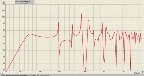
An undamped TL. One can see the fundemental and all the ripple. The nature of the ripple depends on the geometry of the line.
This is the raw response of the pipe, one is not finished yet. Completely unimportant to the discussion is that in this lime the fundemental looks underdamped.
This is typical, (and i wish more people would add damping to their sims, these are not good representations), and we have developed design tricks/tools to deal with this.
Historically (IOnley, Bailey) this was dome via brute force with volume fill damping. Modern design tools (best exemplified by the MJK worksheets), other things have developed to suppress the harmonics without the inevitable loss of bass from just using damping. Most prominant of these is driver offset (Zd), and Mass Loading. The first can pretty much cancel out the hardest to kill 1st unwanted harmonic, and the latter acts to bandpass the terminus.
dave
Dave, You really know alot about acoustic principles and design. Do you think damping the interior walls with damping mat material instead of volume fill would help decrease bass loss and still reduce harmonic resonance. Driver off set seems to alleviate harmonics and diffraction at edges. Don't understand about how mass loading reduces band pass terminus? There are paint on damping that would also reduce resonance problems. Like you said build quality is inportant in transmission design. I use 1 " mdf or 3/4 ply wood. Mdf is really heavy but who moves speakers around. Explain mass load vs band pass terminus please. Thanks for interest and response. I need input on next project transmission design. I will have friend make cabinet because mine always look homemade and wife doesn't like if they don't look pretty. Thanks so much!
Last edited by a moderator:
Paint on damping is for cabinet panels not the airspace so wrong application (i would caution anyone about using anything that increases mass without stiffness but that is a different subject.
How much and how to stuff depends heavily on the specific design. I have drawn an awful lot of TLs, ML-TLs, ML-Voigts, the damping can differ from volume fill to a lining. An extreme example of a voigt, the BIB, requires considerable damping in very specific places as well as the corner loading.
The microTower ML-TL, out big MTMs, and Tysen V2 have volume fill, most Metronomes (a version of an ML-Voigt) usually get away with lining and sometimes little of it (a combination of pipe geometry, Zd, mass-loading, and a downward firing terminus to create the low passes needed to remove most of the ripple, but Mileva and Demetri (ML-Vs) wanr something in-between.
A lot of playing by us and by many, many others have teased out what works… but then we have to throw in the room.
A mass kiaded terminus does act as a band-pass… choking off frequencies above, but like any oyher box with a hole in it, unloads below the tuning so that par tis sort of moot.
First thing to do for your next TL/QW loudspeaker is to choose a driver, or a driver/box combo. Lots of proven designs. So many analysis paralysis can set in. Don’t be afraid to ask questions.
dave
How much and how to stuff depends heavily on the specific design. I have drawn an awful lot of TLs, ML-TLs, ML-Voigts, the damping can differ from volume fill to a lining. An extreme example of a voigt, the BIB, requires considerable damping in very specific places as well as the corner loading.
The microTower ML-TL, out big MTMs, and Tysen V2 have volume fill, most Metronomes (a version of an ML-Voigt) usually get away with lining and sometimes little of it (a combination of pipe geometry, Zd, mass-loading, and a downward firing terminus to create the low passes needed to remove most of the ripple, but Mileva and Demetri (ML-Vs) wanr something in-between.
A lot of playing by us and by many, many others have teased out what works… but then we have to throw in the room.
It does not do that.Driver off set seems to alleviate ... diffraction at edges
Martin J King. (MJK)Don't understand about how mass loading reduces band pass terminus?
A mass kiaded terminus does act as a band-pass… choking off frequencies above, but like any oyher box with a hole in it, unloads below the tuning so that par tis sort of moot.
First thing to do for your next TL/QW loudspeaker is to choose a driver, or a driver/box combo. Lots of proven designs. So many analysis paralysis can set in. Don’t be afraid to ask questions.
dave
Last edited:
Dr Dave, speaker doctor. You certainly make me look silly sometimes but I just like fooling around always doing unconventional ideas.. never really liked playing by the rules , often to my own demise. After all most inventions were created out of mistakes luck and alot of stubbornness to never give up. Though you were talking about actual mass ie. Sand to o a cavity to reduce resonance. Understand it's the port loading . You clarified. The reduction of ripple effect through integrated design principles is key to this TL design. The video I referred to explained the process of trying to align 2 combs to smooth out FR. You clarified offset driver and diffraction . Guess geometry of corners or no corners effects that. Like you said there are so many variables and always tradeoffs in speaker design. What I think sounds great you might hate. We might agree my brother in law's Martin Logan's sound pretty darn awsome in the sweet spot. Sent a new tread yesterday about tactile transducers ie. Actuator applied to big flat light weight panels like poly styrene even cardboard going to pick up a couple for $20 ea 40 watt and play around. That should be very interesting. Thanks for all of your professional advise and future support with some wired question and ideas keep designing . Nano technology on speakers is really getting better Michael
Last edited by a moderator:
Michael,
We discourage people posting their email addresses on the forum. I hve removed many of yours. Please save me the effort.
dave
diyAudio moderation team
We discourage people posting their email addresses on the forum. I hve removed many of yours. Please save me the effort.
dave
diyAudio moderation team
The restricted terminus bandpass nature reduces combing (the primary reason it is used). One needs sufficient amount of low pass from the cabinet out the terminus so that the frequencies that comb never come out. The ripple is causesd by the combing.

There are a huge number of compromises that have to be made in a loudspeaker. Many. Lots. The art in speaker design is the choosing of those compromises that least affect YOUR listening.
Before i discovered single full range loudspeakers i was into ESLs. There biggest issue is finding an amplifier that can live with the highly reactive load.

Note that the power rating of a home hifi loudspeaker is pretty much a useless number with little meaning. Pay no attention to it.
dave
If you fold the line and do not add a corner “reflector” the expansion in the cross-section of the line acts as an additional LP filter. More useful in horns with no damping.Guess geometry of corners or no corners effects that.
There are a huge number of compromises that have to be made in a loudspeaker. Many. Lots. The art in speaker design is the choosing of those compromises that least affect YOUR listening.
Before i discovered single full range loudspeakers i was into ESLs. There biggest issue is finding an amplifier that can live with the highly reactive load.
Note that the power rating of a home hifi loudspeaker is pretty much a useless number with little meaning. Pay no attention to it.
dave
- Home
- Loudspeakers
- Planars & Exotics
- Voigt transmission principle