Hi Forr,
"You didn't and just qualify as "fast" the thermal VC reactions, maybe you could provide more substantiated informations than mine"
It's practically impossible to measure, how am I supposed to measure it ? also I've seen no reference that anybody did it, however with your voice coil you can apply some power there and feel it, right ?
have you looked at stereophile graph carefully ? with all due respect,I'm not here to play semantics with you, I said that the voice coil RESISTANCE is modulated. and I don't like it.
If you think that it's not subject to improvement, then what is it that you do in this thread ? It is the same as saying there's no point in reducing THD from 1% to 0.1%
Hartono
"Do you think the delivered power is often 1W for 12s at home ?"
what do you mean with this question ?
maybe you can try building amp with 1 watt power supply to power 3 way speaker with 89 dB efficiency and let see if you like the result.
what do you mean with this question ?
maybe you can try building amp with 1 watt power supply to power 3 way speaker with 89 dB efficiency and let see if you like the result.
Hartono said:Hi Forr,
"You didn't and just qualify as "fast" the thermal VC reactions, maybe you could provide more substantiated informations than mine"
It's practically impossible to measure, how am I supposed to measure it ? also I've seen no reference that anybody did it, however with your voice coil you can apply some power there and feel it, right ?
have you looked at stereophile graph carefully ? with all due respect,I'm not here to play semantics with you, I said that the voice coil RESISTANCE is modulated. and I don't like it.
If you think that it's not subject to improvement, then what is it that you do in this thread ? It is the same as saying there's no point in reducing THD from 1% to 0.1%
Hartono
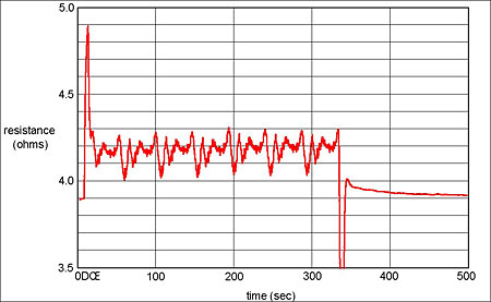
I suspect what we're seeing is simply a measurement artifact. The best clue is the large spikes as the signal is applied and then removed. Those obviously don't represent the "real" DC resistance. I haven't studied his circuit in detail to find where the above-DC stuff is getting in but it clearly is from the graphs.
Dennis H
Hi Forr,
I'm meaning to be rude or anything, but your responses is lacking in "consideration" for the problem in hand, and I'm not very pleased.
you want me to give you some reference material ? ok try "Loudspeaker Design Cookbook" fifth edition , page 21 , 1.72"Dynamic Changes in Frequency Response". By Vance Dickason
it says "The loudspeaker can be expected to perform in accordance with the design tables and formula calculations at 1W power input, but beyond that, as power increases and voice coil temperature increases the characteristics of the driver/box combination will undergo constant dynamic change"
I forgot to mentioned, the phase also change, not only the SPL, dynamically.
Hartono
Hi Catapult,
"I suspect what we're seeing is simply a measurement artifact"
yes it's probably true, I think more measurement and analysis need to be done to know the real mechanism and the impact on the sound reproduction.
"I suspect what we're seeing is simply a measurement artifact"
yes it's probably true, I think more measurement and analysis need to be done to know the real mechanism and the impact on the sound reproduction.
Hi Hartono,
Do you know what is the average listening level at home ?
If you think that there are still thermal issues in voice-coils, there is a solution : current drive. It has the advantage to tame other forms of distortions, even more proeminent. The drawback is the loss of damping but it can be restored by servo, as experimented by Hawksford and by Greiner, both have published details in the JAES.
Jay_WJ said:
I'm a scientist and not a simple person.
Jay_WJ said:
How could I do an experiment when I have no measurement setup?
So no wonder that I couldn't give any scientific, knowledgeable details there.
Well, since you mentioned it, just what type of scientist are you?
An interesting subject to be focused on for someone who has never built a speaker system before. With more experts here chiming in, will you ask them direct questions to satisfy the answer you would rather hear?
Jay_WJ said:
HTG IS---a very closed, narrow circle of people
I have no problem with Jon. A dictator always says that he didn't do anything to force people to adore him, but they, especially a few around him, just did.
I don't understand, either.David Gatti said:FWIW Jay, I dont know why you were expelled based on that thread. Seemed like a reasonable and civilised discussion to me
Hmmm. Perhaps the why is based on reasons outside of that (snapshot) thread?
If you do finally build a speaker system yourself, what would prevent you from measuring this (or any other effect)...yourself? Or are you a scientist who plans on building speakers without ever having to measure?
cheers,
AJ
Hi Forr,
I know some people say that the average listening power is small indeed, some stated in few watts average, but the large transient is what make people need large power amplifier,200 watts or more is not so out of context in home environment.many subwoofer need considerably more.
The problem is this transient power also cause transient heating, which will not be shown in smoothed/averaged testing, as I stated before , unless the cooling is at the exact same rate, the resistance will still be modulated,In resistor specification this is called thermal EMF, usually only specified on precision resistor. using ferrofluid also helps, but is not always suitable for all speaker driver.
If you happen to have the book by Vance Dickason, it also explore how much the voice coil heating affect box and speaker Q (combined ) and also SPL. it's quite substantial.
Yes current drive will mitigate this problem.
And in the case of passive crossover sensitivity, this also can be reduced using active crossover approach.
Best regards,
Hartono
Jay, there are many tool threads here, and one in the htg reference section, but I will suggest some that I have used:
Cheap measurement setup: M-audio mobile pre + Behringer EMC8000 microphone.
Cheap software: speaker workshop, some say its interface is terrible, but it is not too bad to get at least some valid measurement out of it.
You may find schematics for resistor shunts to measure impedence, its not difficult to envision a solution for this without any schematics.
I like Matlab for simulations, people have previously recommended free equivalents to that, theres all sorts of other simulators out there for all sorts of purposes, I use free SiMetrix for my electronics. Svante has all sorts of tools, he is quite the expert. Theres free excel spreadsheet tools out there, lspCad, and all sorts of simulators to do all sorts of things.
If you are willing to do some experimentation, people will generally help you limp along. Svante was quite patient with me when I was trying to design servo feeback using the wrong derivative to measure loudspeaker output.
Lee
Hartono,
I don't make my living as a scientist although I do have a few degrees somewhere in a box. What you are describing is what we in the construction business call "tripping over dollars trying to pick up dimes." In this case, the dimes are the instantaneous VC heating effects and the dollars are the instantaneous increases in Le with increased excursion. VC heating is small potatoes compared to Le (and thus impedance) changes as the VC moves farther away from center. That will have a bigger effect on the frequency response. And that's not to mention the effect Bl and suspension nonlinearities have as you pass 1/2 Xmax.
We can all agree that pushing a driver too hard is a Bad Thing (Martha) but let's get clear on the electro-mechanical mechanisms of the biggest problems.
Dennis H
The problem is this transient power also cause transient heating, which will not be shown in smoothed/averaged testing, as I stated before , unless the cooling is at the exact same rate, the resistance will still be modulated,In resistor specification this is called thermal EMF, usually only specified on precision resistor. using ferrofluid also helps, but is not always suitable for all speaker driver.
I don't make my living as a scientist although I do have a few degrees somewhere in a box. What you are describing is what we in the construction business call "tripping over dollars trying to pick up dimes." In this case, the dimes are the instantaneous VC heating effects and the dollars are the instantaneous increases in Le with increased excursion. VC heating is small potatoes compared to Le (and thus impedance) changes as the VC moves farther away from center. That will have a bigger effect on the frequency response. And that's not to mention the effect Bl and suspension nonlinearities have as you pass 1/2 Xmax.
We can all agree that pushing a driver too hard is a Bad Thing (Martha) but let's get clear on the electro-mechanical mechanisms of the biggest problems.
Dennis H

The sharp spikes that are visible in the Stereophile graph are caused by overshoot from the 1Hz lowpass filter.
It's a shame that they sought to eliminate possibly the most relevant information with a lowpass filter and a long time scale. What if there were short-term peaks of around 5 ohms, or maybe 6 or 7ohms or even more? If the VC is operating near its limit then it could blow in the same way that incandescent light bulbs fail: by rapid localized heating.
CeramicMan said:
The sharp spikes that are visible in the Stereophile graph are caused by overshoot from the 1Hz lowpass filter.
It's a shame that they sought to eliminate possibly the most relevant information with a lowpass filter and a long time scale. What if there were short-term peaks of around 5 ohms, or maybe 6 or 7ohms or even more? If the VC is operating near its limit then it could blow in the same way that incandescent light bulbs fail: by rapid localized heating.
Got a better schematic to show us? Personally, I think the 1 Hz lowpass is too high to get 'correct' data without smoothing. 1 Hz is below the audio band but music changes amplitude in that range.
It's pretty clear from the driver time constants (4 seconds +) posted above that a voice coil in a driver is nothing like a thin tungsten filament suspended in a vacuum when it comes to how fast they heat up when a current is applied. If it were, it would take several seconds for a light bulb to start making light after you flip the switch.
Got a better schematic to show us?
Who's "us"?

Personally, I think the 1 Hz lowpass is too high to get 'correct' data without smoothing. 1 Hz is below the audio band but music changes amplitude in that range.
Why should the averaged data matter in the first place? As far as I can tell, such slow, sub-1Hz, sub-1dB variations don't cause any audible distortion, artifacts or colourations whatsoever. That was established on page one.
We're talking about distortion or whatever other mechanism there might be, by which VC heating could alter the sound in a realistic, perceivable way. After all, people claim that they can hear dynamic compression, therefore it must be caused by something.
I suggested one already: localized heating. Just like a light bulb where a section of the filament heats up faster than the rest. It usually only happens when a high voltage is applied and the filament is still cold.
And why does the time scale matter? Because if the time scale is short enough, high levels of THD and IM distortion become a possibility.
And why does the time scale matter? Because if the time scale is short enough, high levels of THD and IM distortion become a possibility.
Yup. Not just a possibility but a fact. Orders of magnitude larger than very short-term heating effects. As the VC moves more off center, Le, Bl and suspension compliance all change, causing distortion which is very audible. Hifi drivers are just too small to play really loud. A 15" pro mid has 10x the cone area and 1/10 the excursion of a 6" hifi mid at the same SPL so it's less subject to all the evils of too much excursion. Overheating is a minor concern in comparison.
CeramicMan said:[snip]...Say for example, the speaker is playing two tones: a high amplitude 100Hz sine wave, and a softer 1.5kHz sine wave. Temperature oscillation due to the 100Hz tone modulates the amplitude of the 1.5kHz tone, creating side-lobes around 1.4kHz and 1.6kHz.
I wrote that on page one. 🙄
Maybe it can be tested like this:
1) Get a small value resistor, which has a very large heat capacity. Eg: a large number of 1W resistors in parallel. Better still: soak them in an oil bath or something like that.
2) Connect the resistance in series with a raw driver (no box, and away from acoustic reflections).
3) Play a loud midrange sine wave at only one frequency: where the inductive and capacitive reactances cancel out, at say, 500Hz or 1kHz.
4) Measure variations in the resistor/driver voltage ratio.
That should practically eliminate acoustic effects such as cone or motor distortion, as well as Fs.
Say for example, the speaker is playing two tones: a high amplitude 100Hz sine wave, and a softer 1.5kHz sine wave. Temperature oscillation due to the 100Hz tone modulates the amplitude of the 1.5kHz tone, creating side-lobes around 1.4kHz and 1.6kHz.
Once again, for the example you present, heating effects are orders of magnitude below simple cone movement effects when it comes to IM distortion. Nothing to do with motor distortion, just simple Doppler distortion from the cone moving, just like the way a race car changes pitch as it moves past you.
IM (Doppler) distortion % = 0.91 * (max 1-way excursion in mm) * (max freq in kilohertz)
Plugging some numbers into the above, let's say your small cone is moving +/- 3 mm to play the loud 100 Hz tone which is modulating the 1.5k tone.
IM % = 0.91 * 3 * 1.5 = about 4% distortion.
MUCH bigger than any heating effect.
IM % = 0.91 * 3 * 1.5 = about 4% distortion.
MUCH bigger than any heating effect.
There's some very interesting stuff being discussed here, and some very interesting experimental data (I'd love to see comparisons of actual transfer functions and distortion as a function of thermal history for a variety of driver types), but... speaking as a moderator here, I'd appreciate it if the few digs at other people and forums mixed in with the valuable stuff were put aside and the debate remains on the technical aspects- they're interesting enough that they don't need added drama.
Dennis, I had the chance to visit NHT a few weeks ago and saw some of their data on variation of the T-S and electrical parameters with displacement. These would, of course, contribute to driver and driver/box nonlinearity- I'd suspect that not only will the static values change, but the shape of the parameter vs, displacement curve would also change. That might be a more sensitive test. And high-slope passive crossovers could well be more sensitive to this variation.
If I had a laser interferometer setup handy, I'd do it myself. If any of the crew here has that capability, the results could be interesting.
If I had a laser interferometer setup handy, I'd do it myself. If any of the crew here has that capability, the results could be interesting.
SY said:Dennis, I had the chance to visit NHT a few weeks ago and saw some of their data on variation of the T-S and electrical parameters with displacement. These would, of course, contribute to driver and driver/box nonlinearity- I'd suspect that not only will the static values change, but the shape of the parameter vs, displacement curve would also change. That might be a more sensitive test. And high-slope passive crossovers could well be more sensitive to this variation.
If I had a laser interferometer setup handy, I'd do it myself. If any of the crew here has that capability, the results could be interesting.
Hey SY, good to hear from you.
That's the nice thing about modern software like LspCAD. You can take your measurements at different power levels and vary all the XO components over say +/- 5% and see how big the changes really are. A well-designed XO should be relatively insensitive to changes. I think there's no real evidence that 'complex' crossovers are more sensitive to these things than 'simple' crossovers. Maybe a bit of 'urban legend'?
- Status
- Not open for further replies.
- Home
- Loudspeakers
- Multi-Way
- Voice coil heating and the performance of passive XO, plus my funny experience at HTG