What about an isobaric config with the front driver being mounted on the enclosure surface and then a passive radiator directly behind it (like dustcap almost touching motor close) this way theres a small amount of air in between so that the slave follows the active more closely and you get two full voice coils.
Thats probably stupid, but I like coming up with ways to solve a problem.
Thats probably stupid, but I like coming up with ways to solve a problem.
No thanks. I only wanted a casual look at it. But thanks for thinking of it anyway. 🙂phase_accurate said:Hi Circlotron
Are you still interested in the EW+WW article ?
I did a long post about my current build using a different approach... but it has disappeared into the ether.......
put simply, wind another coil on the protruding coil former. I used about 20 turns. This only requires the cone cap being removed, wind on coils and replace cap..
Yes it works,but unless anyone is interested i am not going to retype the long version where I describe it in detail
........oztules
put simply, wind another coil on the protruding coil former. I used about 20 turns. This only requires the cone cap being removed, wind on coils and replace cap..
Yes it works,but unless anyone is interested i am not going to retype the long version where I describe it in detail
........oztules
I did a long post about my current build using a different approach... but it has disappeared into the ether.......
put simply, wind another coil on the protruding coil former. I used about 20 turns. This only requires the cone cap being removed, wind on coils and replace cap..
Yes it works,but unless anyone is interested i am not going to retype the long version where I describe it in detail
........oztules
Would love to see more, motional feedback in the bass is a huge remaining opportunity in many systems. For the second coil is there reasonable flux linearity but low density due to the positioning? How did you verify performance?
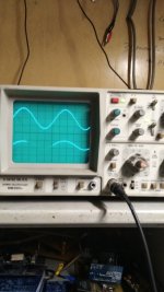
Badman, seeing as your interested, I went out and took a range of photos of the dual trace scope.
The camera decided to loose the memory card for reasons I can't figure out, so I decided to use the phone... a huawei y7..... min photo size is 6mb... not sure what the forum takes will look into it.
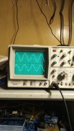
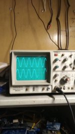
In the meantime, the scope shows the original signal into the speaker, and the emf produced by the coil on the front. I will show how an augmented field changes the amplitude of the signal, but not the waveform... when I sort the pic problem.
So it works beautifully, and only takes 20 minutes to make and get running... truly amazing.
It has a single drawback, in that ( was not expecting this to be so great ) as you sweep the frequency, the ampltude of the return wave increases as the frequency increases, at first blush, it looks to be about 3db/octave.... so a roll off filter will fix that too.
This would appear to be a function of the velocity of the cone movement. As V increases, so does the emf.... and V increases as F increases. ( the cone has to travel twice the distance in the same time effectively to follow the frequency as you go an octave faster).
At this stage I have not gone too far into the correction problem, as I just wanted to see it work.
Hooked it up and it does.... not without some heartburn, but that has been solved too.
Will get this project better displayed in the very near future, and anyone with spice stuff can design whatever they need in the way of mitigating filters as they seem fit.
So thats the story so far, it turned a crappy plywood box into a decent sounding box.
The mid and tweeter drive naturally, and the freq splitter is a clone of the Phillips 22rh587... of which I have had 6 for the last 40 years or thereabout... so I do know what to expect.
The augmentation is in the form of a simple cylinder of steel, sitting on top of the original magnet in the coil former. It effectiely brings the magnet field closer to the coil of wire, and increases the output to about 20% of the input emf into the speakers.. way to high really, but is is easy to control...
Does that give you an idea of what I was doing.
A better explanation is coming as soon as I get a way of making low res pictures from the silly high res that the phone camera has, or I get the olympus working again
.........oztules....... Flinders Island... Australia
amendments to above post.
"increases output to 20%... really is 1/20th of spkr emf...... eh it happens.
Further looking into it, it would appear I was premature with the 3db/octave... is is more complex than that I think.
As I swept the freq up much more than the band I was interested in, it became clear that as always, lots of things are happening at the same time.
As the frequ rises from in the 30 hz range , it does indeed increase in magnitude as compared to the cone input... but it is a refection of natural resonance changing the cone differentials for the same power input... ie cone efficiency changes with the frequency down near the natural resonance.... and the rate of change the coils sees in the magnetic field... faster the change, higher the emf... except at the same time, the travel is less, so there is a whole bunch of things happening in there.
The nett result, s that in the narrow band we are interested in for MFB, it is not a huge deal, and most should be mitigated easily.
For my purposes, the result is very nearly the same as my phillips boxes... and thats very very good..... will post a pic or two in the post reply box to see if I can master that....
.......oztules
Seems to have worked!
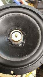
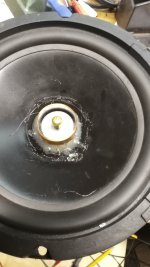
Ok, here is a pic of the prototype first try cone to prove the idea.
It was a cone I didn't care if I destroyed. It has an aluminium former ( later I used a transformer paper former )
The block/cylinder of steel in the inside with the bolt for removal purposes is just a machined cylinder, with the shape of a cotton reel. I reasoned that if I made the "waist" of it very much slimmer, the main flux would be emanating from the top that you can see.
This would give me a "local" field... not sure if that is the best design by a country mile, but was an idea. It works as you can see from the above pics of the waves.
The lower freq like 100hz as seen here is much lower in amplitude, and much harder to get a pic of on these old cro's
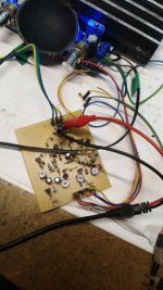
And here is the splitter board I made for these tests.. derived from the phillips boxes I have ( 587 )
I may do a full post if that is worthwhile for others to play with. It deos seem a very easy and useful way to get the signal for MFB
...... oztules
Ok, here is a pic of the prototype first try cone to prove the idea.
It was a cone I didn't care if I destroyed. It has an aluminium former ( later I used a transformer paper former )
The block/cylinder of steel in the inside with the bolt for removal purposes is just a machined cylinder, with the shape of a cotton reel. I reasoned that if I made the "waist" of it very much slimmer, the main flux would be emanating from the top that you can see.
This would give me a "local" field... not sure if that is the best design by a country mile, but was an idea. It works as you can see from the above pics of the waves.


The lower freq like 100hz as seen here is much lower in amplitude, and much harder to get a pic of on these old cro's

And here is the splitter board I made for these tests.. derived from the phillips boxes I have ( 587 )

I may do a full post if that is worthwhile for others to play with. It deos seem a very easy and useful way to get the signal for MFB
...... oztules
Well Badman, this will be the final post for the night. The running commentry is over for the day.
I have to say a big thank to you for asking the question about verifying the results.
Todays results thus far are all about the test speaker on the bench, looking at just the feedback characteristics.
The actual box tested one is slightly different in the respect that it has no "steel cotton reel" inside the former like the one pictured. I had decided due to laziness to just run the box version without the steel magnetic field shaper, knowing I would lose gain, but didn't care as I had plenty on the MFB input amp on the splitter board.
As I said, the test box sounds very good..... but now I know why.
As a last set of tests, I took the steel center out, and lost about 6db or more..... but I gained a substantial amount of new knowledge..... yep.... my test cone was full of foibles regarding ampltude and frequency......
When I took the steel insert out of the former, I lost gain... but I also got a perfectly linear response..... all the way up to 3khz.... and I also learned I'm a clutz. My laziness made my test box look good and I didn't know any different.
I also learnt that the phillips splitter board does NOT have a 10db/octave as I thought I read in the notes.... but about 3db/khz roll off on the bass circuit.
So they roll the bass out at 3db/khz .... only went to 3khz, but looks pretty linear.... it is the treble and mid that gets the 10-12db/octave from the looks of it... can't speak dutch though....
So it is as easy as I did on the test box. just wind some coils on the top of the former, heat gun glue.. and your done. Whatever output you want in mv/watt input, just add more hair thickness wire.. thats it. It looks linear as all get out..... and tracks the signal perfectly nicely.
There is a small phase change as we go from low freq up to 2khz, and I lost interest after that freq.......but it is only about 7% at worst, and straightens up to maybe 3% as we go to 1khz......
I have never looked at the phillips boxes to see what they actually get in the way ... well of anything really... they sound great, I leave them alone but for replacing electro's etc..... 40 odd years does no one any good.
I'm amazed..... and amazed I lucked into this arrangement. My magnetic augmentation was a bust... justy didn't know it until I researched it further... not my strong point at all.
............oztules
Interesting stuff! Thanks for the write-up. I am not surprised that the coil functioned better once you removed the steel- it seems like you'd get more linear flux but at a lower level further away from the motor, due to the flux falloff with distance behavior.
Very cool, keep at it!
Very cool, keep at it!
My question about this sort of feedback mechanism is, how much does the signal you get from either a winding near the voice coil, or the voice coil former approach represent cone motion, rather than just transformer action between the voice coil & sensor coil? As for the low output of the one turn conductive former approach, do the opposite of what ribbon speakers do; use a step up transformer for it.
In commercial MFB woofers the magnetic field and the coil of the sensor are often orthogonal to the voice coil in order to minimise interference. Keep in mind that if it is not done right one might still get flat frequency response (which can be had by EQing much more easily) but increased THD because the linearity of the feedback path dominates the linearity of the whole loop.
If you scroll down a little you can see how Backes and Müller does it:
The Sub Woofer
Regards
Charles
If you scroll down a little you can see how Backes and Müller does it:
The Sub Woofer
Regards
Charles
Does this link work? https://www.diyaudio.com/forums/the...wtorch-preamplifier-iii-1079.html#post5620204
Great stuff. Thanks.The lower freq like 100hz as seen here is much lower in amplitude, and much harder to get a pic of on these old cro's
But the eye is poor at seeing distortion that way. An X-Y plot might show more - esp for driver amplitudes that push the limits of suspension linearity.
The big reveal is using tone bursts. You wouldn't believe the obvious and dramatic improvement MFB will show on a scope.
The object of the effort is to see some weird stuff in the feedback trace because that's the weird stuff the cone is doing when it ought to be doing just nice sine motion.
Numerous MFB threads new and old in the Subwoofer forum. That's because MFB is helpful really in the low frequencies. And that's because that's where the distortion occurs and also because cone-motion feedback (esp VC) does not tattle on all the bad sounds coming from the driver.
Don't forget, the MFB concept applies right to the bottom frequencies. So at low freq when your box is diminishing or distorting the output, MFB to the rescue. So MFB extends the range, driver and amp permitting.
But the greatest effect as many who try MFB can swear is the great improvement in transient impact in the bass... which is what we all want.
B.
Last edited:
There are a number of ways to do MFB, mostly feeding back on the motion of the dust cap, so to speak. Great debates about methods because there are clear trade-offs in design.
While I have long favoured using the voice coil itself (in a bridge), it is open to the same criticisms as this thread in twice-chewing the same magnetic field. With all the graduate student theses devoted to more linear magnetic field development, pretty risky to invent your own cotton-reel shaped magnet, as much as I sincerely admire the experimental élan of oztules, I don't think it is a good approach.
Fair to say that current favourite is using inexpensive precision accelerometer devices (nearly always is has been the ACH-001) glued to the cone.
B.
Redrawn more intelligibly, in Klippel's system in Figure 2 you have something partly Wheatstone Bridge and partly current MFB. But I think he means it as an means of correcting the input signal, not as a feedback circuit.
I think he is playing patent-go-round because the error signal is pretty much the same as current MFB except for being inverted. Huh?
Curiously, his "state estimator" module bears some resemblance to the way you balance a Wheatstone Bridge MFB.
B.
Last edited:
- Status
- Not open for further replies.
- Home
- Loudspeakers
- Multi-Way
- Voice coil *former* generates motional feedback voltage?
