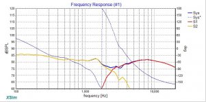
Decided recently to build the Classix II (and learn along the way about crossover designing). Thought about putting the exact components for the Classix II build by Paul Carmody on VituixCAD and the response graph is completely different than his!
I have used the official FRD and ZMA files for both drivers. What could the problem be?

I have used the official FRD and ZMA files for both drivers. What could the problem be?
Attachments
Were the FRD & ZMA files you used generated from actual measurements of the drivers in the Classix II box?
If not, they won't take account of baffle step & diffraction effects, which may be skewing your curves.
If not, they won't take account of baffle step & diffraction effects, which may be skewing your curves.
As above. Looks like baffle diffraction isn't included in your model.
Also, regarding the dip at the crossover. Do you have the correct offsets and microphone distance set in VituixCAD?
Also, regarding the dip at the crossover. Do you have the correct offsets and microphone distance set in VituixCAD?
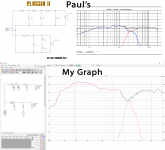
I've done the same exercise in Xsim just using makers' data and using fptrace to generate the tweeter frd and zma files: they look quite different!
The one on the left is Xsim, the right is Paul's actual measurement. Exactly the same XO parts and layout were used in each.
Geoff
The one on the left is Xsim, the right is Paul's actual measurement. Exactly the same XO parts and layout were used in each.
Geoff
Attachments
Last edited:
Now try the makers data in VituixCAD...
And don't neglect the advice already given, you will find that the results you are getting are for the reasons stated above.
And don't neglect the advice already given, you will find that the results you are getting are for the reasons stated above.
Hi WastD,
you can not do it like that.
The Speaker response depends on the circumstances.
You took an infinite baffle responce, i guess.
Try the diffraction tool in vituix cad to simulate the driver on the according baffle first.
Also you need to simulate the encloser in Vituix Cad and merge it with result of the diffraction tool. Dont forget to also simulate the impedance of the speaker in the encloser. Dont take free air impedance.
First of all, your drivers in vituixcad are showing as emitting from the same point in space, I.e. you have them all set to 0,0,0 on the x,y and z axis.
Set the woofer to y=-150mm, and perhaps z=+/- 30mm and see what happens. As the true acoustic centres of the drivers determine the phase relationship between them at the crossover. As the woofer is a deeper cone, it’s acoustic centre is further back than the tweeters.
Set the woofer to y=-150mm, and perhaps z=+/- 30mm and see what happens. As the true acoustic centres of the drivers determine the phase relationship between them at the crossover. As the woofer is a deeper cone, it’s acoustic centre is further back than the tweeters.
Last edited:
- Home
- Loudspeakers
- Multi-Way
- VituixCAD and Classix II