Dearest Forum!
I have two FRS8 flying around and have also just found out about the fantastic Foamcore board possibilities, so I decided to give it a try with a wall mounted, very flat transmission line speaker.
The highth and width of the speaker shall be Din A 2, which means 42x60cm.
The depth of the speaker can be choosen, but should not exceed 10 cm, in general, the smaller the depth, the better for the wall mounting purpose.
The concept should be a transmission line system with a tuning at around 64 hz, and now my big question is, how shall I calculate it. I want to build a single folded design, so in general, there are three questions open:
1. Where to place the seperation wall, how long shall it be and in which angle?
2. How big shall the opening of the tube be? Does only the cm2 matter, or also the shape of it?
3. My idea was to place the driver in the upper left corner of the box. Is this a good idea?
This is a "just for fun" project, but it would be nice if they would sound nice at the end.
Thanks guys for your help, I really apreciate it.
Attached to this, you can find a most beautiful drawing of the ruff idea of the project.
Cheers!
Use Hornresp's Loudspeaker Wizard to find the desired length, parabolic taper to get a terminus [exit] that's at least Sd*0.5 to fit your dimensions [if possible], then in the 'schematic' window, click on 'file', then use the 'export horn data' tool to choose a rectangular horn where it will allow you to select the desired width or depth to recalculate the dimensions and in your case a 'uni' width flare to export to .txt file.
GM
GM
You can take the TS parameters and put them in Godzilla's BIB calculator spreadsheet. Then flatten the design and make a FIB (Flat BIB). Here is an example of one I did with TC9.
http://www.diyaudio.com/forums/full...e-fostex-craft-handbooks-514.html#post3342958
I ended up bifurcating it but still following basic BIB cross sectional area and length.
Plan:
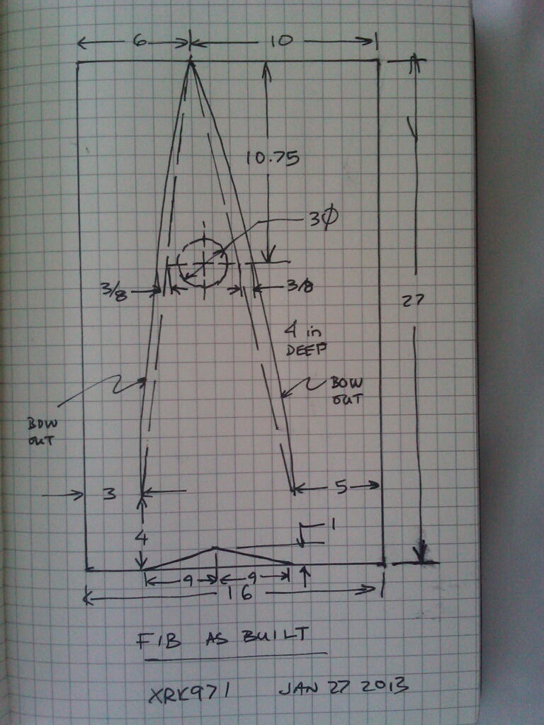
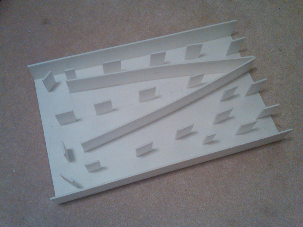
Looks like this inside:
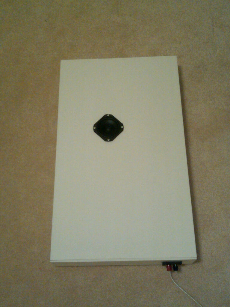
I still use these speakers - mounted in baby's room and they do a great job.
http://www.diyaudio.com/forums/full...e-fostex-craft-handbooks-514.html#post3342958
I ended up bifurcating it but still following basic BIB cross sectional area and length.
Plan:
Looks like this inside:
I still use these speakers - mounted in baby's room and they do a great job.
Schlumpfpeter's design would work if the base of the box was triangular; this to obtain same area in the knee (bent) and to do the tapering correctly.
Exit ( terminus in TL terminology....!?!? ) would then happen to be a hole same diam. as the speaker.
Nice !
Dimensions shall also be restricted about 20 %, so about 50 cm H X 30L
Exit ( terminus in TL terminology....!?!? ) would then happen to be a hole same diam. as the speaker.
Nice !
Dimensions shall also be restricted about 20 %, so about 50 cm H X 30L
You can take the TS parameters and put them in Godzilla's BIB calculator spreadsheet.
As presented, this isn't a good idea based on what the OP asked for since the BIB is based on the tuning to be a full octave below Fs + even if tuned to Fs it may not be the correct one either.
GM
Hi guys,
Thank you all very much for all your answers!
planet10, I googled leonard software, but did not find a simulation program, only somthing for cnc cutters. Can you further specify the program please?
xrk971, this looks good! I somehow would like to see my speaker turning out quite the same as yours. I found the spreadsheets, thanks for that. But how do I turn the "normal" BIB design into a flat one?
picowallspeaker, what do you mean with a triangular base? And what do you mean with "this to obtain same area in the knee (bent) and to do the tapering correctly.
Exit ( terminus in TL terminology....!?!? ) would then happen to be a hole same diam. as the speaker"??
I think you might have some very good ideas there, so I would love to understand what you are talking about.
Thank you all and have a nice weekend,
SP
Gm, I somehow cannot follow you. What does Sd stand for? Anyway, thanks for the software recomendation, I will check it.
The BIB calculator gives depth and width. Calculate cross sectional area and preserve that while reducing depth to whatever you like for a "flat" speaker. Don't make it too flat or you get back reflections that make it sound congested. In any case use felt or foam padding around driver area to reduce back reflections.
GM thanks for your input as well. I have some problems understanding your technical language (sorry, not a native speaker).
Especially this part : "parabolic taper to get a terminus [exit] that's at least Sd*0.5 to fit your dimensions" makes my brain start spinning.... What is a parabolic tapper and what does Sd stand for?
Especially this part : "parabolic taper to get a terminus [exit] that's at least Sd*0.5 to fit your dimensions" makes my brain start spinning.... What is a parabolic tapper and what does Sd stand for?
You're welcome!
In recent decades, driver specs are defined by its T/S parameters and 'Sd' is the driver's effective piston area and as a general rule we want a 'vent' area [Av] = to at least 50% of it: TS Parameters (Thiele/Small Parameters) - Home Theater Forum and Systems - HomeTheaterShack.com
When a box has parallel sides and a flat surface [board divider] is installed perpendicular to one parallel side and angled in relation to the other parallel side it creates a parabolic taper from one end of this acoustic TL to the other contrary to a conical one that many mistake it for. In other words, like a BIB.
XRK's construction though has curved dividers, so is probably some form of hypex, i.e. has a horn flare factor [M or T depending on who you 'ask'] somewhere between a hyperbolic [M = 0.5] and exponential [M = 1.0] as opposed to being one or the other, technically making it an offset driver compression horn whereas the BIB is a simple offset driver expanding TL [pipe horn], which generally requires more damping than a properly designed horn.
Hornresp's Loudspeaker Wizard can accurately sim either, making anyone with basic computer skills a horn designer that is superior to most folks that did it for a living before the internet and readily available computer software became available.
GM
planet10, I googled leonard software, but did not find a simulation program
http://www.diyaudio.com/forums/software-tools/220421-transmission-line-modelling-software.html
dave
GM, thanks for your clarifications. For the ease of the building, I would like to go with a straight transmission line design. It can get folded once or twice or even three times, if necessary. But the straight TL this is not a must, it is a nice to have, but if another design is more suitable, than I would go with thht as well. I will play around with the modelling software. But isn´t a "non straight" (i.e. non parallel sides) TL not a transmission line anymore? I always understood TL as a tube with parallel walls.
Dave, thank you very much for the link. I downloaded the program and did the first modelling.
Unfortunately, the interface is quite the opposite of an intuitive workflow. I got it so far, the only thing I am missing is how I could clearify the depth of the box.
I cannot just somehow type in the meaussurements, don´t I? I only found the area to be typed in, but not, for exampel hight, length and depth. I only need those three for a TL, cannot be so hard, so what am I missing?
Cheers guys, have a good week.
Ok, I think I got it now.
I attached a screenshot of my model. I think it could work out quite well, but I would apreciate if someone could give it a quick look, just to see if I made an obvious major mistake.
Cheers!
Am I right with the assumption that the graph on the left just shows the output of the rear end of the transmission line and is not including the midrange and highs which are directed straight from the front of the speaker?
Last edited:

Guys, thank you so much for all your help.
I have finally found the best solution for my Speaker, it is a single folded straight transmission line design. I wanted to tune it to around 65 Hz and and the length of a 120cm long straight pipe almost matches this to the spot.
I already got the foamcore board for one box, the other foamcore board will arrive shortly")
The design is dead simple with a Din A 2 foamcore board, as it is only a single folded design with a straight pipe. The depth of the speaker will be 5 cm, so really a flat wall speaker.
I also considered a double folded BIB design, but for the ease of building, I ended up with the following straight TL design:
You can see a screenshot of the design below:

Thanks!
I have finally found the best solution for my Speaker, it is a single folded straight transmission line design. I wanted to tune it to around 65 Hz and and the length of a 120cm long straight pipe almost matches this to the spot.
I already got the foamcore board for one box, the other foamcore board will arrive shortly
The design is dead simple with a Din A 2 foamcore board, as it is only a single folded design with a straight pipe. The depth of the speaker will be 5 cm, so really a flat wall speaker.
I also considered a double folded BIB design, but for the ease of building, I ended up with the following straight TL design:
You can see a screenshot of the design below:
Thanks!
You're welcome!
Hmm, the tapered one looks pretty good, the straight ones not so much. Typically, by the time all the ripple is adequately damped there's little/no real [mid]bass left when tuning almost an octave below Fs. I don't remember if this software calculates Xmax limited power handling or not, but neither will there be any to speak of unless a BIB with vent is used since it takes a lot of acoustic power to offset the lack of a large Xmax.
Anyway, foam core is cheap and for all I know 1-2 W maybe all you need, so let us know how well it works in your app.
GM
Have you seen this design? VIFAntastisch ! Der Wandlautsprecher, Projekte der Nutzer / Eigenentwicklungen - HIFI-FORUM
I think it might be similar to what you are proposing. I have built a pair of these and they perform very well.
Graham.
I think it might be similar to what you are proposing. I have built a pair of these and they perform very well.
Graham.

- Status
- This old topic is closed. If you want to reopen this topic, contact a moderator using the "Report Post" button.
- Home
- Loudspeakers
- Full Range
- Visaton FRS8 Flat transmission line speaker - how to calculate?