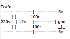
Last edited:
Feed the 12VAC to a bridge rectifier, giving you approx. 18V peak. Afterwards filter the DC with two large capacitors in series. grounding the center point of the two caps will give you a symmetric +-9V supply. Equalizing resistors parallel to the caps may be used, but often are omitted in the low-voltage regime.
If the preamp is sensitive to overvoltage, use a pair of regs to get the 9V down to 6V.
Rundmaus
EDIT: Aaaaah, been reading to quick-and-dirty. Does the preamp need 6-0-6 AC or a symmetric +-6VDC supply?
If the preamp is sensitive to overvoltage, use a pair of regs to get the 9V down to 6V.
Rundmaus
EDIT: Aaaaah, been reading to quick-and-dirty. Does the preamp need 6-0-6 AC or a symmetric +-6VDC supply?
Resistive tapping will only work if the current draw is very stable and, if not balanced, accurately known. Better to buy the right transformer, or make a balanced DC supply and feed that in instead.
Thanks for the quick reply guys 🙂 The preamp came as an kit without the trafo. It has one 7805 and a 7905 psu. I have a 12v ac adapter that I could use if I could divide the ac hoping I didnt have to do anything with the circuit 🙂 Here is the preamp:
LCD Remote Stereo Volume Control CH Selector with Aluminium Case for DIY Audio | eBay
LCD Remote Stereo Volume Control CH Selector with Aluminium Case for DIY Audio | eBay
In this case I would not fiddle around. Buy a small 2x6VAC toroidal and use the whole kit as intended.
Rundmaus
Rundmaus
ok 🙂 But I see they offer a 9v and 12v 30w trafo for this kit. Is not 30w a little overkill for this preamp. That's what I use in my JLH Class A Headphoneamp. Wouldn't a dual 6v trafo with 10va be enough?
6VAC should give a little less than 9VDC after rectification. Given there are no large mains fluctuations, this should be enough headroom for a 5V reg. If in doubt, use dual 9V transformer or replace regs by low-drop ones.
Rundmaus
PS. 30W seems a lot for a preamp. Does the manual state a current consumption?
Rundmaus
PS. 30W seems a lot for a preamp. Does the manual state a current consumption?
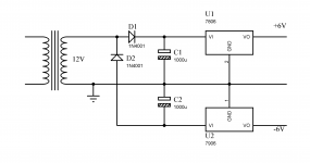
This will be half-wave rectification for each of the rails with very poor ripple performance. I doubt the regs will manage a nice DC from that.
Rundmaus
Rundmaus
This will be half-wave rectification for each of the rails with very poor ripple performance. I doubt the regs will manage a nice DC from that.
Rundmaus
The ripple is the double of a full-wave rectifier, but even with a current draw of plus/minus 60 mA (the PGA draws only about plus/minus 10 mA), the ripple is only 1 V with 1000 uF capacitors, and that is no problem for the regulators. And the ripple can be reduced by using larger capacitors....
Ok, but where's the advantage compared to using bridge rectification and grounding the center point of the two caps?
Rundmaus
Rundmaus
Ok, but where's the advantage compared to using bridge rectification and grounding the center point of the two caps?
Rundmaus
Please read Post #1
I reread post #1 and still don't see the advantage.
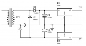
I attached your schematic, changed to bridge rectification. Can you explain what your reference to post #1 meant and why half-wave rectification for each rail is preferable to the bridge rect. version?
Rundmaus
I attached your schematic, changed to bridge rectification. Can you explain what your reference to post #1 meant and why half-wave rectification for each rail is preferable to the bridge rect. version?
Rundmaus
Attachments
A capacitive centre-tap doesn't do DC imbalance very well. The pair of half-wave rectifiers doesn't care about DC imbalance so would be fine.
Ah right... One could use equalizing resistors parallel to the caps, but that would make it more complicated and dissipate a lot of power...
Rundmaus
PS. But anyway, as there is rectification, filtering and voltage regulation already implemented on the board the thread opener bought, both solutions are out of the game. Getting an appropriate transformer would be the best way, IMHO.
Rundmaus
PS. But anyway, as there is rectification, filtering and voltage regulation already implemented on the board the thread opener bought, both solutions are out of the game. Getting an appropriate transformer would be the best way, IMHO.
- Status
- Not open for further replies.
- Home
- Amplifiers
- Power Supplies
- Virtual ct on a trafo with no ct

