Try to obtain a copy of the Printed Circuits Workbook Series by Clyde F. Coombs Jr. (Hewlett Packard), which covers, in great detail, their assembly methods - very informative.
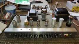
That's a 500 series plugin, what type is/was it? They are beuatifully made asare the Tek 500 scopes,works of art. I have two on my test bench, a 585A and a 545B,both in daily use. Although big, heavy and power hungry these scopes are well worth restoring, they are very low noise, great for valve amp testing some capable of 600v IP. A lot of these are unfortunately stripped of their valves and scrapped, which is daft, as the valves are most likely at very low emission having been powered up for years.
This vintage test gear is an inspiration to us valve amp builders, I try to achieve the same level of workmanship,it goes some way to alleviate the guilt of scrapping an old 545A.
Andy.
This vintage test gear is an inspiration to us valve amp builders, I try to achieve the same level of workmanship,it goes some way to alleviate the guilt of scrapping an old 545A.
Andy.
Attachments
"Bouyer" ?
Hi huggygood,
never would have thought that Bouyer did anything else than church PA's 😉.
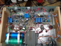
Btw, I'm quite impressed by that wiring accurateness. Mine resembles the pic in #10 rather than Bouyer's, see, for instance, the guitar amp that I built using the chassis and the iron of a Hammond AO-68 from a scrapped cheesy K-100 organ.
Best regards!
Attachments
Yes that French but of kit is sexy.
The guy I got both pieces of gear has a whole bunch of them, he just threw them in when I bought some stuff. They were pretty much untouched since the 70s. They still had their calibration tags. The military amp was unopened when I got it.
He has still got all sorts, but most of his valves have been cherry picked. He has a multiple variac cabinet that has about 4 on it, plus planet meters. It’s the size of a radiogram.
A lot of these are unfortunately stripped of their valves and scrapped, which is daft, as the valves are most likely at very low emission having been powered up for years.
This vintage test gear is an inspiration to us valve amp builders, I try to achieve the same level of workmanship,it goes some way to alleviate the guilt of scrapping an old 545A.
Andy.
It is especially daft considering the most worthwhile parts are those amazing transformers. I have a couple which were saved from a scrapped chassis which are being built into amplifiers now 🙂
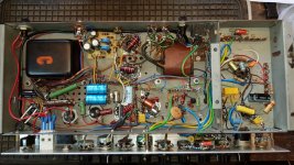
That's looking good handwound, could I suggest you have a go at some traditional lacing, it really tidies up the wiring, looks good and was used on the Tek 500 scopes in question. See - Lace Cord to bundle Wire Harnesses - YouTube & https://mathscinotes.com/wp-content/uploads/2014/01/021c99s2c08.pdfI try with my wiring, this is a pre almost complete.
Some of the old Tek scopes can't be salvaged it's true, the tfmr's as you say are amazing and excellent quality like all the parts in these scopes. Pete Millet used a salvaged Tek 500 tfmr for a hefty bench PSU,see -http://www.pmillett.com/HV_bench_supply.htm & here's some data on the various 120 type tfmr's - Tek power transformersIt is especially daft considering the most worthwhile parts are those amazing transformers
Andy.
Yes I have a couple of 120-0140-00, I believe they are from the 545? Soon they will power a GM70 amplifier 😀
Yep,the 545A & B I think. One thing occurred to me though,if you connect some of the HV windings in series to get high HT/B+, I think there's a possibility of burning out the windings. AFAIK series connection of windings of different current rating can result in shorted windings, as the wndg with the least I rating bears the brunt. That said the wndgs on theses 120 tfmr's are pretty generous current rating wise,so maybe no worries. I've done it but not with any heavy loadsYes I have a couple of 120-0140-00, I believe they are from the 545?
Thanks for the concern but no worries that has been taken into account!
- The windings I'm going to use to get the high voltage can easily carry that much current
- Every winding is going to receive it's own fuse as an extra precaution
- The windings will be sequentially switched into the powersupply by relays
- Individual rectifiers and cap banks before they get stacked
So also upon being switched on there won't be some insane inrush current due to an empty capacitor bank
Tektronix was kind enough to document their transformers very well. For example this is the 120-140-00, even the amount of turns and where they are positioned respectively to each other can be found here!
https://i.imgur.com/Xcbl1rJ.png
With shunted out dropping resistors? Stacking the various power supply's is the way to go rather than series connecting the windings as you say, it's what Tek did after all.The windings will be sequentially switched into the powersupply by relays
Yeah, don't you love old Tek gear, very good documentation unlike modern built stuff. Look forward to seeing your amp build.
Andy.
No don't worry I mean stacking the supplies like TEK did 😀 and yes there will be a resistor on each winding to limit surges too! I almost forgot about that but it is on the pcb that''s on order
Last edited:
I'd not use dropping resistors, but, depending on the desired output voltage, I'd let the circuitry automatically select the tap of a series connected secondary in order to minimize power loss and heat at the series device.
Best regards!
Best regards!
The PCB you mentioned sounds interesting, if you have one spare I might be interested in buying one.
Not sure if we're talking about the same thing, the dropping resistor I was on about is just after the HT secondary winding, prior to a fuse and bridge rectifier to delay HT/B+ and limit current surge into the reservoir caps. It's switched/shunted out by a time delayed relay, aloows the heaters to warm up a bit too before full HT/B+ is applied to anodes etc.I'd not use dropping resistors
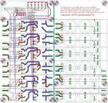
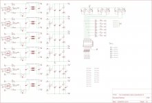
Diabolical Artificer, you can contact V4lve lover (the one from the free gerber thread) since he drew it for me.
FR4 slinger calling in.
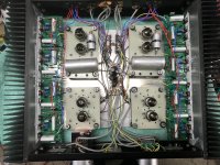
Heres the Board i drew for Gideon, still thinking out a power sequencer, i cant be asked to get the arduino out, so HEF4xxx it is.
Ive put some CNY64 over the fuses, so you have the option of detecting blown fuses .
Heres the Board i drew for Gideon, still thinking out a power sequencer, i cant be asked to get the arduino out, so HEF4xxx it is.
Ive put some CNY64 over the fuses, so you have the option of detecting blown fuses .
Attachments
- Home
- Amplifiers
- Tubes / Valves
- Vintage professional and military wiring