Hello,
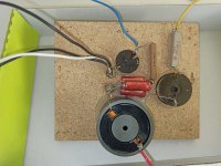
I decided to refresh my old the speakers, the new dumping, the wiring capacitors ... But when I pulled out the crossover I was confused by the design.
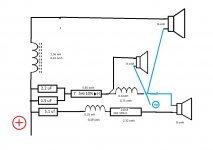
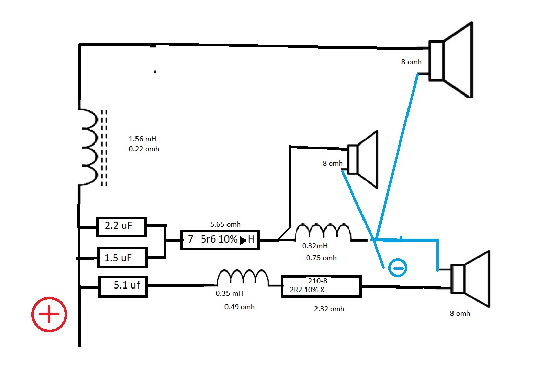
I would be grateful if you would take a look at the photos and the drawing I made and tell your opinion if everything is all right before I buy the capacitors. I measured and wrote the values of the coils and resistors in the drawing. Maybe I can put in better resistors so please advice.
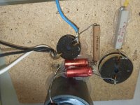
It confuses me that the capacitors 2.2 and 1.5 are in the series, it also seems to me that the bass does not have a capacitor, I also do not understand the point of soldering the negative pole wire before the coil of the twitter speakers.
I don't have much knowledge in electronics, especially I don't know the logic of crossover design and I don't know if anyone has ever worked on that crossover before.
The speakers are Pilot V-3 (German speakers from the early 80's)
I don't want to change the characteristics, I just want to improve them.
I will use Mundorf mcap evo oil Capacitore, and keep the ferrite coil on the bass.
All tips and ideas are welcome
I decided to refresh my old the speakers, the new dumping, the wiring capacitors ... But when I pulled out the crossover I was confused by the design.
I would be grateful if you would take a look at the photos and the drawing I made and tell your opinion if everything is all right before I buy the capacitors. I measured and wrote the values of the coils and resistors in the drawing. Maybe I can put in better resistors so please advice.
It confuses me that the capacitors 2.2 and 1.5 are in the series, it also seems to me that the bass does not have a capacitor, I also do not understand the point of soldering the negative pole wire before the coil of the twitter speakers.
I don't have much knowledge in electronics, especially I don't know the logic of crossover design and I don't know if anyone has ever worked on that crossover before.
The speakers are Pilot V-3 (German speakers from the early 80's)
I don't want to change the characteristics, I just want to improve them.
I will use Mundorf mcap evo oil Capacitore, and keep the ferrite coil on the bass.
All tips and ideas are welcome
Attachments
I think the resistors will be OK, no need to replace them.Maybe I can put in better resistors so please advice.
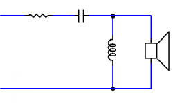
They work together. It is the same as 1 capacitor, value 3.7uF.It confuses me that the capacitors 2.2 and 1.5 are in the series,
This is a second order filter..I also do not understand the point of soldering the negative pole wire before the coil of the twitter speakers.
Attachments
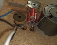
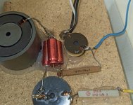
I would replace the woofer inductor, the one enclosed in ferrite: from a trial I've made once with an inductor of that type, the sound coming from the woofer was "saturated" and "metallic". A coil wound up in air or with ferrite core would sound better IMO. To reach the same DC resistance ( 0.22 Ω) you would need a thicker gauge of wire, because of the ferrite encapsulation trick ( it augments inductance)
This shell core is gapped, so maybe not too different to solenoid core. Also it would benefit by containing stray flux.
I'd just bring all the speaker terminals out of the box and make adjustments from there. No binding posts, just solid core enameled copper wire. But that's me
It's not wildly different from the old SEAS 503 three way, by the looks of things:
SEAS Kit 503
Simple but effective. 🙂
SEAS Kit 503
Simple but effective. 🙂
thanks for the answers, the crossover will be external, i will use solid core wire 0.5mm for high and 1mm for mid and bass. The ferrite coil stays until I get the 2mm wire so I'll try to wind it myself. For the terminals I will use WAGO 221, it may look ridiculous to someone, but it has a very good connection and is made of copper, so I think it's better than all the fancy gold plated connectors that are made of brass.
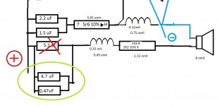
How critical is it to put 5.6 uf instead of 5.1 because it changes the price if I use 0.47+4.7 = 5.17?
How critical is it to put 5.6 uf instead of 5.1 because it changes the price if I use 0.47+4.7 = 5.17?
In a second order crossover, component tolerances have an effect as a square root.
Which is to say, 10% tolerance has a 5% effect on the filter:
I'd get 3.9uF and 4.7uF and be done with it. The little adjustment caps look pricey!
I doubt my old ears will hear any difference! The theory says the film caps will sound a bit brighter than NPE due to lower internal resistance of the order of 0.5R. 🙂
Hello,
I decided to refresh my old the speakers, the new dumping, the wiring capacitors ... But when I pulled out the crossover I was confused by the design.
I would be grateful if you would take a look at the photos and the drawing I made and tell your opinion if everything is all right before I buy the capacitors. I measured and wrote the values of the coils and resistors in the drawing. Maybe I can put in better resistors so please advice.
It confuses me that the capacitors 2.2 and 1.5 are in the series, it also seems to me that the bass does not have a capacitor, I also do not understand the point of soldering the negative pole wire before the coil of the twitter speakers.
I don't have much knowledge in electronics, especially I don't know the logic of crossover design and I don't know if anyone has ever worked on that crossover before.
The speakers are Pilot V-3 (German speakers from the early 80's)
I don't want to change the characteristics, I just want to improve them.
I will use Mundorf mcap evo oil Capacitore, and keep the ferrite coil on the bass.
All tips and ideas are welcome
please do not show capacitors with resistor symbol
its confusing
- Home
- Loudspeakers
- Multi-Way
- Vintage crossover, Help