I built this amp at the period of the lottery and it seems to be working fine, however I discovered last night that the left channel’s output transistors and thus the sinks are hot but the right channel’s are not.
Measured the voltage from the zener to ground and both channels measure 20v
And both channels have the same volume or output.
This was not like that before, though noticed that both channels behaved the same, both hot.
So, could it be the zener gone bad? Or nothing to worry about. Thanks.
Measured the voltage from the zener to ground and both channels measure 20v
And both channels have the same volume or output.
This was not like that before, though noticed that both channels behaved the same, both hot.
So, could it be the zener gone bad? Or nothing to worry about. Thanks.
If one channel is cold, then its not conducting the current. Even if it makes sound, its still deffective, no longer classA. You need two equal channels. So definitelly something to worry about.
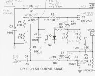
Is this the amplifier?

If yes, when you measured the voltage at the zener relative to ground, was it at the Z1 anode?
What is the voltage drop across R1, R2?
If you adjust the P1 trimmer, does the voltage at the zener anode relative to ground change?
If yes, when you measured the voltage at the zener relative to ground, was it at the Z1 anode?
What is the voltage drop across R1, R2?
If you adjust the P1 trimmer, does the voltage at the zener anode relative to ground change?
Anode as per the guide and yes the p trimmer reacts, will measure those voltages in the resistors. Thanks,
Check the optocoupler, no light, no current.
Let's see what voltage drop on R1/2 is.
Measure both channels, voltages between ground and various spots, post in the schematics, blue for good, red for bad channel, respectively.
But do not rush. We do not want to do harm.
Let's see what voltage drop on R1/2 is.
Measure both channels, voltages between ground and various spots, post in the schematics, blue for good, red for bad channel, respectively.
But do not rush. We do not want to do harm.
Preliminary findings
Checked all resistor values in both channels and the only difference is in R7 which reads 4.7k as per the schematic in the left channel -the supposedly good one- and only 2.9k in the right channel.
And as far as the opto lights I cannot see them in either channel even with the lights out. That is a very small led in there. So even without the light on in the left channel it gets hot…. Unless I am missing something.
I plan to check the voltages later on. Thanks again…
Delta V R1/R2 right channel -without class A- 0.1v, left channel 1.2v
Delta V R7/R8 both channels 10.2/17 v
Delta V cases to G 2SJ28-0v both channels
Delta V cases to G IRF259_35.7v 31.8v ea. Channel basically same
Delta R cases to G 2SJ28-right channel 2.8 ohm left channel 31.8 ohm
Delta R cases to G IRF250 left channel 31.8 ohm right channel 33 ohm
No opto led visible even with magnifier and lights out
Thanks for help

- Home
- Amplifiers
- Pass Labs
- vFET P channel issue question…