Recently I got this player for cheap and I open it up to clean it and study it. The player works quite well and the CDM4 is still a quite reliable laser pickup.
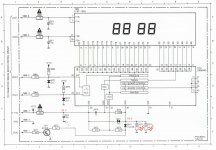
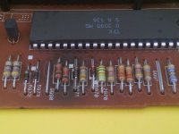
I noticed, though, an odd circuit design for VFD driver board (refer to the schematics). V-FTD on the lower left side is 33 Volt (generated in the PSU by a 15V regulator with a 18V zener diode on its reference connection); that voltage is fed to the VSS pin of the IC driver but the nearby VDD pin requires only 18V. That level is obtained with a 15V zener diode (6971), which drops the voltage from 33 to 18V, and two 1.8 kOhm resistors (3971 & 3972) which keep a constant current flow through the diode. The problem is that each resistor is traversed by a 10 mA current and thus dissipates 180 mW; under normal use, the two resistors get pretty hot and the result can be seen in the second picture. The two resistors are quite tiny and I guess they are capable of handling only 0.25 W; moreover this CD player has a power switch that actually just cuts some voltages to make it appear it is turned off, but indeed most of the circuits are still powered. In the VFD board, only the AC power to drive the VFD is cut, all the other voltages (including V-FTD) are still on. So basically those two poor resistors are kept hot close to their max power handling spec for years and years !
To mitigate the issue I tried with two 4.7 kOhm resistors, but the zener does not reach the target voltage of 15 V and the 18 V reference voltage increases to 26V keeping the display off. I though 8mA would be enough for the diode but indeed it appears it needs 20 mA, so I placed again two 1.8 kOhm resistors but this time opting for 0.5 W resistors. They still gets warm but at least they should be more capable of handling 180mW of dissipated power.
In the end .. what the heck Philips ? what is the point of toasting the PCB with two tiny resistors ??!?!?.
Attachments
If there's the space, I'd suggest stepping them off the board.
The fact they survived indicates they were fit for purpose [emoji28] the board going a little black isn't uncommon for power supply resistors in gear from that era.
The fact they survived indicates they were fit for purpose [emoji28] the board going a little black isn't uncommon for power supply resistors in gear from that era.
No room to offset the resistors from the board and the copper traces are pretty weak: out of four pads, three disintegrated while desoldering. The new resistors are actually big enough to better dissipate the heat
But why not use a real switch on the mains to really shut down the player when off ? Why keeping basically 80% of the circuitry constantly powered on ?
But why not use a real switch on the mains to really shut down the player when off ? Why keeping basically 80% of the circuitry constantly powered on ?